
High-resolution surface plasmon microscope that includes a heterodyne fiber interferometer

a plasmon microscope and heterodyne fiber technology, applied in the field of high-resolution surface plasmon microscopes, can solve the problems of limited image stability and sensitivity as obtained using these techniques, affecting the stability of the interferometer and the quality of the image, and reducing the overall size of the microscope and optical adjustments thereof, so as to improve the stability of the interferometer and the quality. , the effect of eliminating all mechanical supports for the optical elements

Inactive Publication Date: 2012-01-26
CENT NAT DE LA RECHERCHE SCI +1
View PDF3 Cites 8 Cited by
  • Summary
  • Abstract
  • Description
  • Claims
  • Application Information

AI Technical Summary

Benefits of technology

[0030]It has the advantage, compared to known surface plasmon microscopes, of greatly reducing the overall size of the microscope and optical adjustments thereof, since it enables elimination of all mechanical supports for the optical elements of the interferometer.
[0031]Moreover, the microscope of the invention greatly and significantly improves the stability of the interferometer and the quality of the light beams employed, meaning the measurement and reference beams and the interferometer beam, which enables greatly improved sensitivity and image quality.
[0038]The polarization conversion effected by the polarization converter has the particular advantage of enabling an image to be produced in differential mode, which enables further improvement of the contrast and dynamic range of the images obtained. It is then possible to use the polarization converter to polarize the excitation beam alternately in pure p (radial polarization) mode and in pure s (azimuth polarization) mode and to scan with the measurement beam alternately polarized in pure p mode and in pure s mode the metal layer linearly, alternately, and synchronously with the alternating polarization of the excitation beam.
[0042]The microscope of this particular embodiment of the invention advantageously enables imaging by producing surface plasmon interference between the reflected beam generated by the measurement beam and the reflected beam generated by the reference beam.
[0046]Finally, the microscope of one embodiment of the invention may include a polarizer between the means for detecting the interferometer beam and the second end of the fiber for guiding said interferometer beam, in particular to increase image contrast in the linear polarization configuration.

Problems solved by technology

However, the resolution of those systems, which is limited by lateral propagation of the plasmon, is relatively low, of the order of only a few tens of micrometers at visible wavelengths.
Without special processing of the beam, imaging is virtually impossible.
Moreover, the image stability and sensitivity as obtained using these techniques are limited and generally unsatisfactory for viewing objects of very small size, in particular sizes of the order of a few tens of nanometers, as may apply in biology.
Moreover, other microscopy techniques such as optical coherence tomography (OCT) microscopy as described in the document US 2004 / 100636 can neither rectify those insufficiencies nor be combined with current surface plasmon technologies given that the nature of the observed light beams is different, in particular in terms of amplitude and phase distribution, which are not homogeneous with the surface plasmon, and which therefore cannot be observed in OCT microscopy, which relies on the observation of beams of light in which amplitude and phase variations are uniform.

Method used


Image

  • High-resolution surface plasmon microscope that includes a heterodyne fiber interferometer
  • High-resolution surface plasmon microscope that includes a heterodyne fiber interferometer
  • High-resolution surface plasmon microscope that includes a heterodyne fiber interferometer

Examples


Embodiment Construction

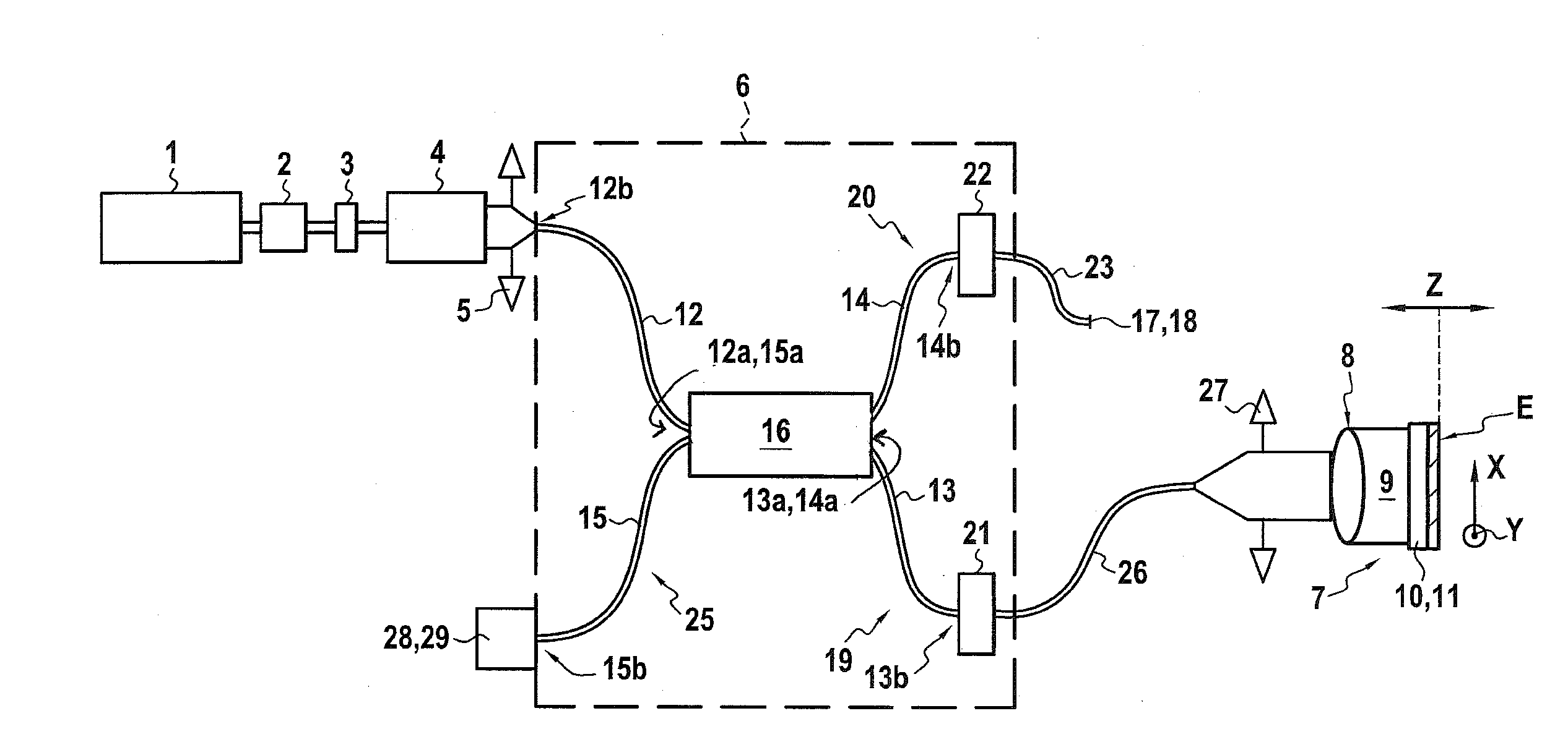
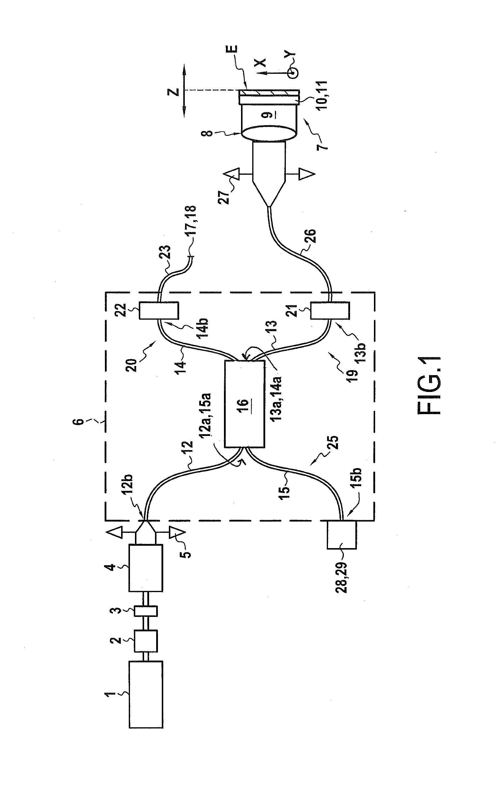
[0053]The present invention proposes a new high-resolution surface plasmon microscope configuration for the observation in air and in aqueous media of nanoparticles and molecules with no fluorescent markers. In this configuration, the microscope includes a heterodyne interferometer consisting essentially of optical fibers, which is novel.

[0054]Referring first to FIG. 1, the microscope of the present invention firstly includes a coherent light source 1, that chosen in the particular example shown being an amplitude-stabilized polarized helium-neon monomode laser. This light source is not limiting on the invention, however, and the use of other types of coherent light source may be envisaged.

[0055]The light source 1 emits a laser beam for exciting a surface plasmon that is injected and directed via a heterodyne interferometer 6 into an optical coupling medium 7 including, in the FIG. 1 example and in a standard manner for a surface plasmon microscope, an objective lens 8 with a high n...


PUM


Abstract

The present invention relates to a high-resolution surface plasmon microscope including a heterodyne interferometer (6) for splitting an excitation light beam into at least one reference beam and at least one measurement beam directed toward a coupling medium (7) to generate a surface plasmon, said heterodyne interferometer consists essentially of guide optical fibers (12, 13, 14, 15) optically connected at a first of their ends to an optical coupler (16) and each also optically connected at their second end to a light source (1), an optical coupling medium (7), an element (17) for reflecting the reference beam, and means (28) for detecting an interferometer beam, respectively.

Description

TECHNICAL FIELD OF THE INVENTION[0001]The present invention relates to a high-resolution surface plasmon microscope including a fiber-optic heterodyne interferometer, i.e. an interferometer consisting essentially of optical fibers.[0002]The technical field of the invention is that of designing imaging systems and methods for detecting small refractive index variations in an observation medium and / or dielectric objects with a size of the order of a few nanometers not necessarily having noteworthy optical properties (fluorescence, luminescence, localized plasmonic resonance, or Raman resonance), located close to a surface and immersed in a dielectric medium, notably in air or an aqueous medium.PRIOR ART[0003]A surface plasmon is a surface electromagnetic wave that propagates in an interface between a metal and an observation dielectric medium.[0004]Excitation of the surface plasmon requires polarized incident light and a coupling medium with a metal / dielectric medium interface at a pa...

Claims


Application Information

Patent Timeline
IPC IPC(8): G02B21/00
CPCG01B9/04G01N21/553G01B2290/70G02B21/18G01B9/02002G02B21/0092
Inventor ARGOUL, FRANCOISEBERGUIGA, LOFTIFAHYS, AUDREY
Owner CENT NAT DE LA RECHERCHE SCI
Learn More