Driving circuit and display

A technology for driving circuits and circuits, applied in static indicators, instruments, etc., can solve problems such as large EMI noise, achieve the effects of reducing EMI noise, reducing high-order harmonic components, and preventing rapid changes

Inactive Publication Date: 2009-12-23
RENESAS ELECTRONICS CORP
View PDF1 Cites 2 Cited by
  • Summary
  • Abstract
  • Description
  • Claims
  • Application Information

AI Technical Summary

Problems solved by technology

This charge and discharge current flows from all the outputs of the liquid crystal driver IC simultaneously in synchronization with the latch pulse, so it becomes a sharp peak current, causing large EMI noise

Method used


Image

  • Driving circuit and display
  • Driving circuit and display
  • Driving circuit and display

Examples


Embodiment 1

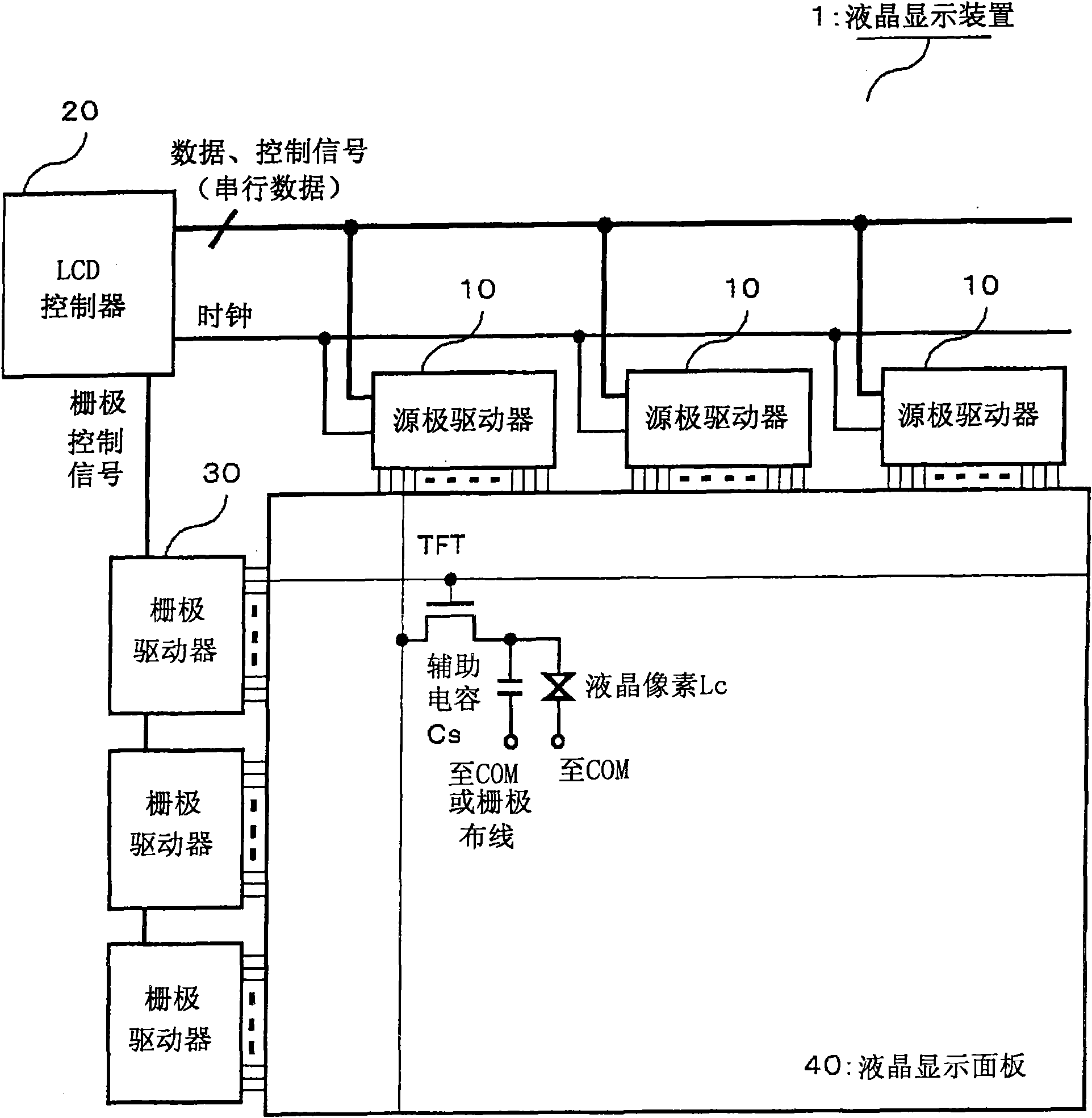
[0033] figure 1 is a diagram showing the configuration of a liquid crystal display device according to a first embodiment of the present invention. exist figure 1 Among them, a liquid crystal display device 1 includes a plurality of source drivers (source-side liquid crystal driver ICs) 10, a timing controller (LCD controller) 20, a plurality of gate drivers (gate-side liquid crystal driver ICs) 30, and a liquid crystal display panel. 40.

[0034] The LCD controller 20 supplies clocks, serial data composed of data (image data) and control signals to the source driver 10 , and supplies gate control signals to the gate driver 30 . In each thin film transistor TFT in the liquid crystal display panel 40 , the source is driven by the source driver 10 , and the gate is driven by the gate driver 30 . The drain of the TFT is connected to a common mode wiring COM and the like via a liquid crystal pixel (liquid crystal portion) Lc and a storage capacitor Cs.

[0035] In the liquid...

Embodiment 2

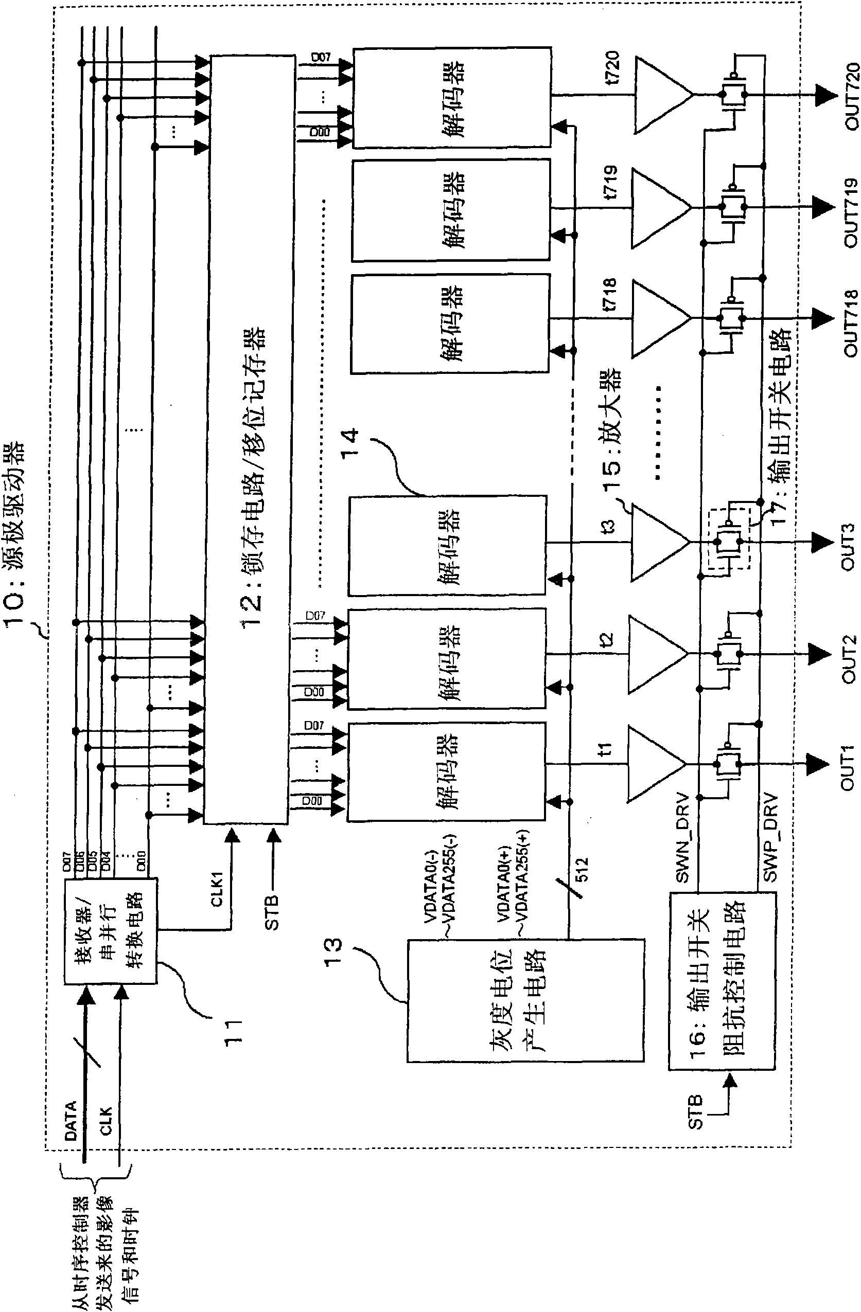
[0051] Figure 6 is a diagram showing the structure of a source driver according to a second embodiment of the present invention. Figure 6 The source driver shown differs from the source driver in the first embodiment in that a plurality of gray-scale potentials generated by the gray-scale potential generation circuit 13 (in this example, VDATA 255(+), VDATA 128(+ ), VDATA 0(+), VDATA 128(-), VDATA 255(-)) are input to the output switch impedance control circuit 16a. The output switch impedance control circuit 16a generates a staircase waveform in the output switch impedance control period using these input grayscale potentials, and controls the impedance of the output switch circuit 17 in a staircase manner.

[0052] in addition, Figure 7 It shows the relationship between the power supply voltage, the common mode voltage, and the gradation potential in a normally black (Normally Black) type liquid crystal display device with a fixed common mode voltage (VCOM).

[0053] ...


PUM


Abstract

A liquid crystal display in which it is possible to reduce the EMI noise ascribable to high harmonic contents in a charging / discharging current is disclosed. The liquid crystal display includes a source driver 10. The source driver includes output terminals (OUTn) that drive a liquid crystal panel, amplifiers 15 that amplify a video signal and output switching circuits 17 each connected between an output of the amplifier 15 and the output terminal. The source driver also includes an output switch impedance control circuit 16 that controls the switching operation of the output switching circuits 17. When turned on during the operation of switching the output switching circuit 17, the output switch impedance control circuit 16 exercises control to progressively lower the impedance of the output switching circuit 17.

Description

technical field [0001] The invention relates to a driving circuit and a display device, in particular to a driving circuit for reducing EMI (Electro Magnetic Interference) noise and a display device using the driving circuit. Background technique [0002] Liquid crystal display (LCD) is characterized by thinness, light weight, and low power consumption, and is widely used in OA, people's livelihood, and industrial fields as a flat panel display necessary in the information and communication age. Generally, such a liquid crystal display device is equipped with a liquid crystal driver IC (liquid crystal driver circuit) having a grayscale potential generating circuit, a decoding circuit, an amplifier, and the like. Wherein, a plurality of gray-scale potentials are generated by the gray-scale potential generating circuit. And, corresponding to the image data signal, any one of the plurality of gray-scale potentials is selected by the decoding circuit. The gray potential select...

Claims


Application Information

Patent Timeline
Patent Type & Authority Applications(China)
IPC IPC(8): G09G3/20G09G3/36
CPCG09G3/3648G09G2330/025G09G2330/06G09G3/3688G09G2310/027G09G2310/066G09G3/3614G09G3/3696
Inventor 梅田谦吾
Owner RENESAS ELECTRONICS CORP
Why Eureka
Try Eureka