High-speed multi-channel clock data recovery circuit

A clock data recovery, high-speed clock technology, applied in electrical components, pulse technology, automatic power control, etc., can solve problems such as narrow tuning range, inappropriate multi-phase signal high-speed transmission, etc., to achieve wide adaptability and programmable capability strong effect

Active Publication Date: 2009-12-23
SANECHIPS TECH CO LTD
View PDF0 Cites 24 Cited by
  • Summary
  • Abstract
  • Description
  • Claims
  • Application Information

AI Technical Summary

Problems solved by technology

[0008] In view of the above-mentioned shortcomings, the purpose of the present invention is to provide a high-speed multi-channel clock data recovery cir

Method used


Image

  • High-speed multi-channel clock data recovery circuit
  • High-speed multi-channel clock data recovery circuit
  • High-speed multi-channel clock data recovery circuit

Examples


Embodiment Construction

[0040] In order to better understand the present invention, the present invention will be further described below in conjunction with the accompanying drawings and specific embodiments.

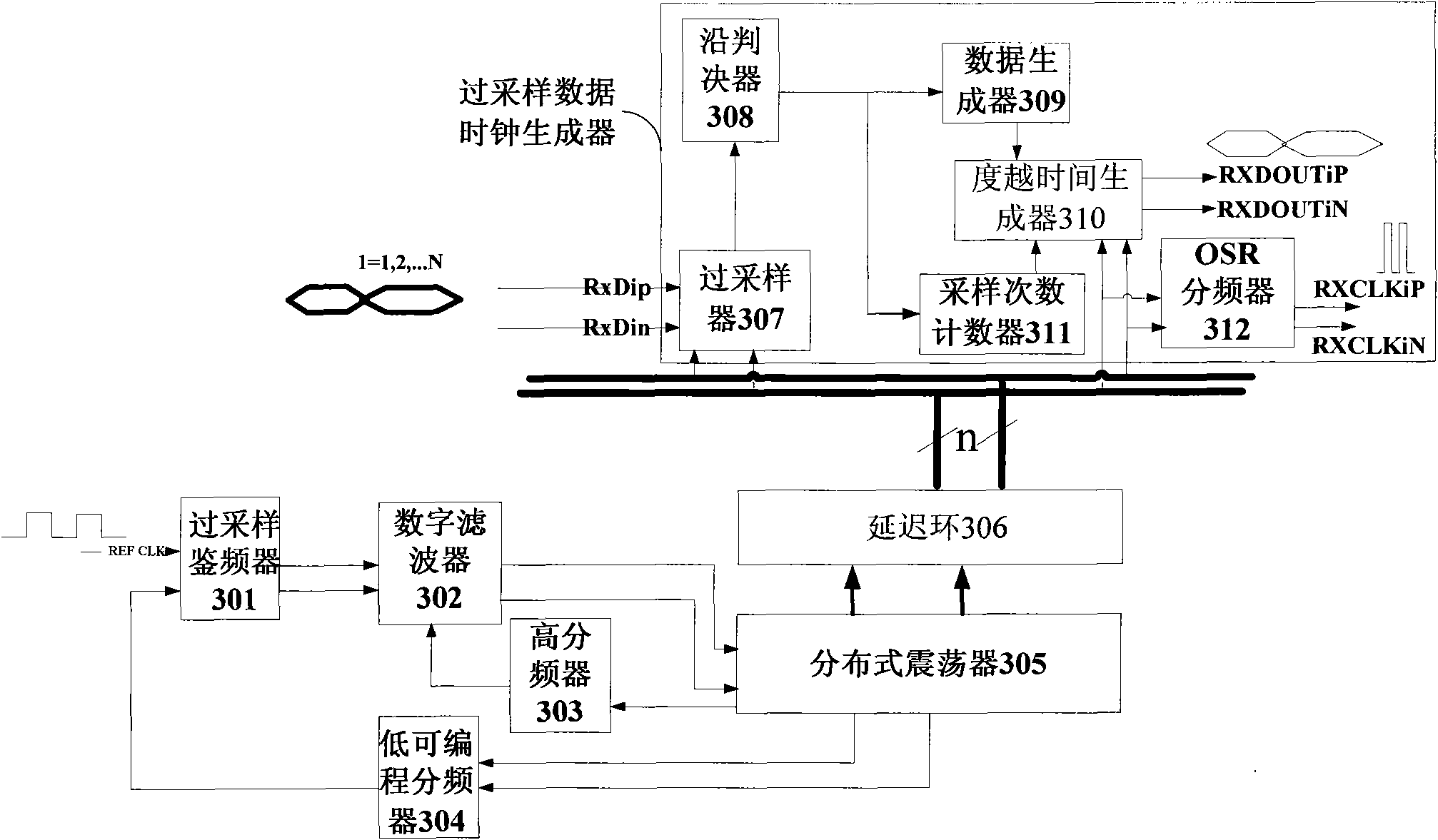
[0041] see image 3 , the high-speed multi-channel clock data recovery circuit of the present invention comprises oversampling discriminator 301, digital filter 302, distributed oscillator (DOSC) 305, low programmable frequency divider 304, high frequency divider 303 and n(n is a natural number) oversampled data clock generators. Wherein, the distributed oscillator 305 is a fully differential distributed oscillator; each oversampled data clock generator includes a delay loop 306, an oversampler 307, an edge decider 308, a data generator 309, a sampling frequency counter 311, a over time generator 310 and OSR divider 312 . see Figure 5 , the delay loop 306 includes a phase detector filter 3060 and a first delay 3061 , a second delay 3062 , a third delay 3063 , . . . , an nth delay 30...


PUM


Abstract

The invention discloses a high-speed multi-channel clock data recovery circuit. The circuit comprises: an oversampling frequency discriminator which is used for receiving a reference clock, and outputting a digital signal after frequency discrimination; a digital filter which is used for receiving and processing the digital signal, and then outputting a comparing control signal; a distributed oscillator which is used for receiving the comparing control signal and generating a high-speed clock signal; a first frequency divider and a second frequency divider which are used for receiving the high-speed clock signal, wherein, an obtained result is transmitted to the oversampling frequency discriminator after the high-speed clock signal is processed by the first frequency divider, and a clock signal which is needed in an operation performed by the digital filter is generated after the high-speed clock signal is processed by the second frequency divider; a delay loop which is used for receiving the high-speed clock signal and generating n pairs of clock signals; and n oversampling data clock generators each of which receives a pair of clock signals output by the delay loop and one channel of high-speed data corresponding to the pair of the clock signals, and processes and recovers the clock signals and the high-speed data corresponding to the clock signals. The high-speed multi-channel clock data recovery circuit has the advantages of strong programmability and wide adaptability.

Description

technical field [0001] The invention belongs to the field of microelectronic circuits, in particular to a high-speed multi-channel clock data recovery (CDR, Clock and Data Recovery) circuit. Background technique [0002] In the design of electronic circuits, data transmission and reception are usually transmitted at high speed through optical fibers or backplanes or between chips, while the processed data is usually relatively low-speed, so a large number of SERDES (serial-to-parallel conversion circuits) are required for serial-parallel Conversion and parallel-to-serial conversion, in which the design and application of the CDR circuit is very critical. The CDR circuit recovers the clock in the transmitted serial high-speed data and extracts the data, and then converts it into low-speed parallel data as needed. [0003] Traditional high-speed (set to high-speed at frequencies exceeding 1Ghz) CDR circuits include frequency detectors, phase detectors, charge pumps, filters, ...

Claims


Application Information

Patent Timeline
IPC IPC(8): H03L7/08H03K5/00
Inventor 易律凡
Owner SANECHIPS TECH CO LTD
Why Eureka
Try Eureka