Electro-hydraulic servo valve for prestage independent type jet flow pipe

A jet tube, self-contained technology used in servo motor assemblies, valve details, multi-port valves, etc.

Active Publication Date: 2011-03-16
SHANGHAI HENGTUO HYDRAULIC CONTROL TECH
View PDF3 Cites 0 Cited by
  • Summary
  • Abstract
  • Description
  • Claims
  • Application Information

AI Technical Summary

Problems solved by technology

[0003]1. The receiver of the split jet tube structure is installed on the valve sleeve. hole, and requires that the long hole must be centered with the receiver hole. The long hole is characterized by a small diameter and a large length, so it is extremely difficult in actual processing. If the machining deviation is too large, the long hole on the receiver hole and the valve sleeve Failure to communicate will cause the parts to be scrapped, and unavoidable small errors will cause insufficient flow area between the receiver hole and the long hole on the valve sleeve, which will affect the recovery efficiency of the pre-stage and make the quality of existing products difficult. ensure;
[0004]2. During the assembly and commissioning of the electro-hydraulic servo, due to the split structure, there are factors that interfere with each other in the zero adjustment of the torque motor, nozzle and valve core , which greatly increases the difficulty of debugging;
[0005]3. During maintenance, if the servo valve produces zero deviation, the zero adjustment of the torque motor, nozzle and valve core will also affect each other, causing the operator to be very It is difficult to judge the cause of the failure, which leads to a large increase in maintenance workload;
[0006]4. The feedback rods of the existing electro-hydraulic servo valves all adopt curved rod structure, which is not only difficult to process, but also has poor load-bearing conditions

Method used


Image

  • Electro-hydraulic servo valve for prestage independent type jet flow pipe
  • Electro-hydraulic servo valve for prestage independent type jet flow pipe
  • Electro-hydraulic servo valve for prestage independent type jet flow pipe

Examples


Embodiment Construction

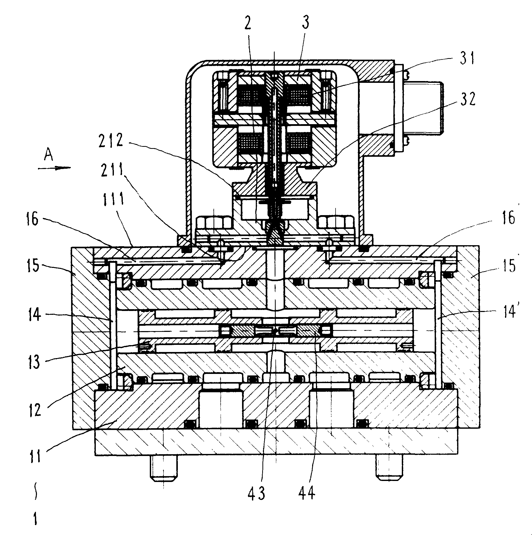
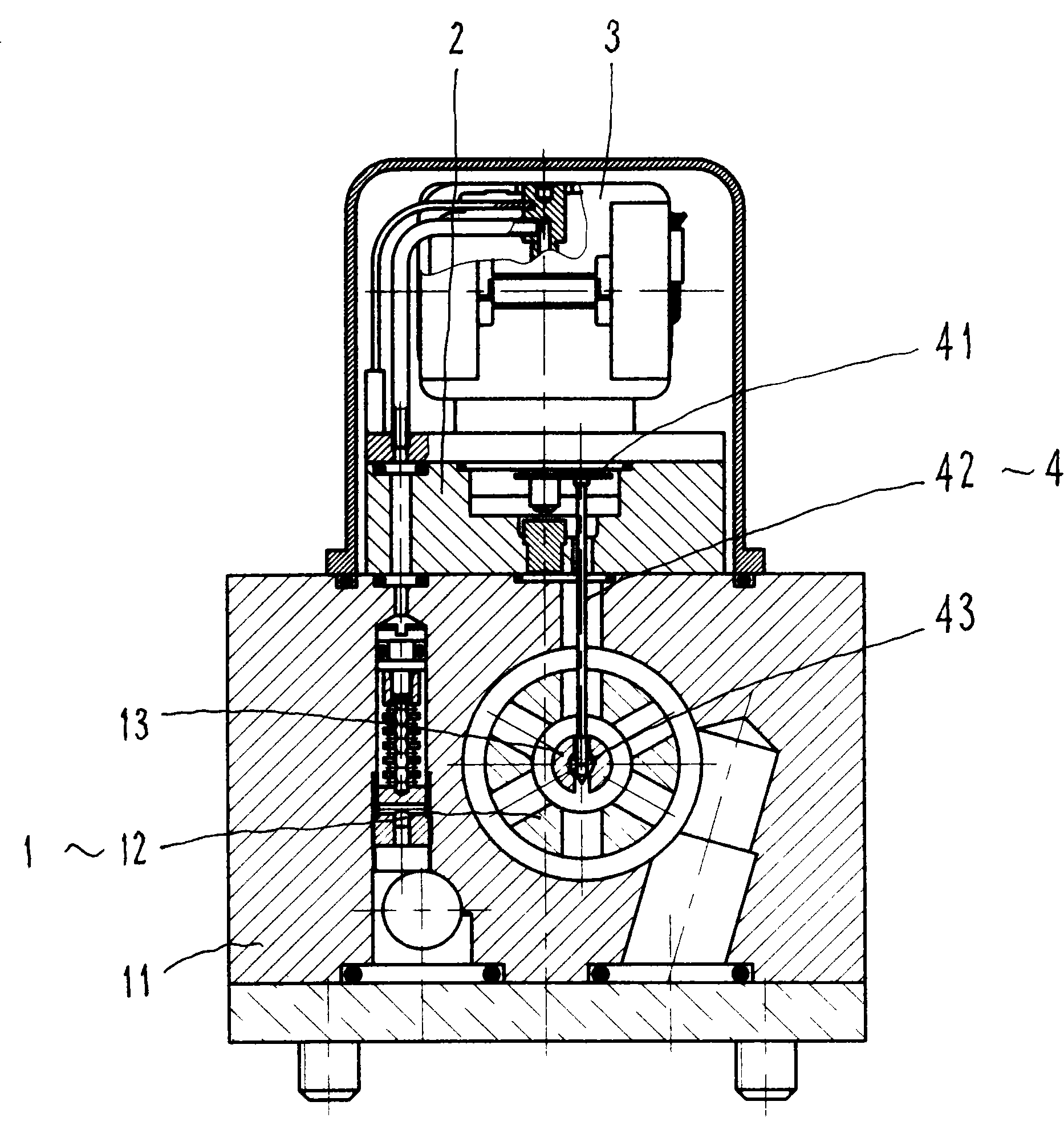
[0019] refer to figure 1 , 2 , 3, 4, the pre-independent jet tube electro-hydraulic servo valve includes a main valve 1, a pre-stage jet tube 2, a torque motor 3 and a feedback lever 4, and the valve body 11 of the main valve 1 is fixed with a pre-stage The jet tube 2, the pre-stage jet tube 2 is fixedly equipped with a torque motor 3, the upper end of the feedback lever 4 is connected to the pre-stage jet tube 2, the lower spherical end 43 of the feedback lever 4 is in contact with the adjusting bolt 44 of the main valve 1 .

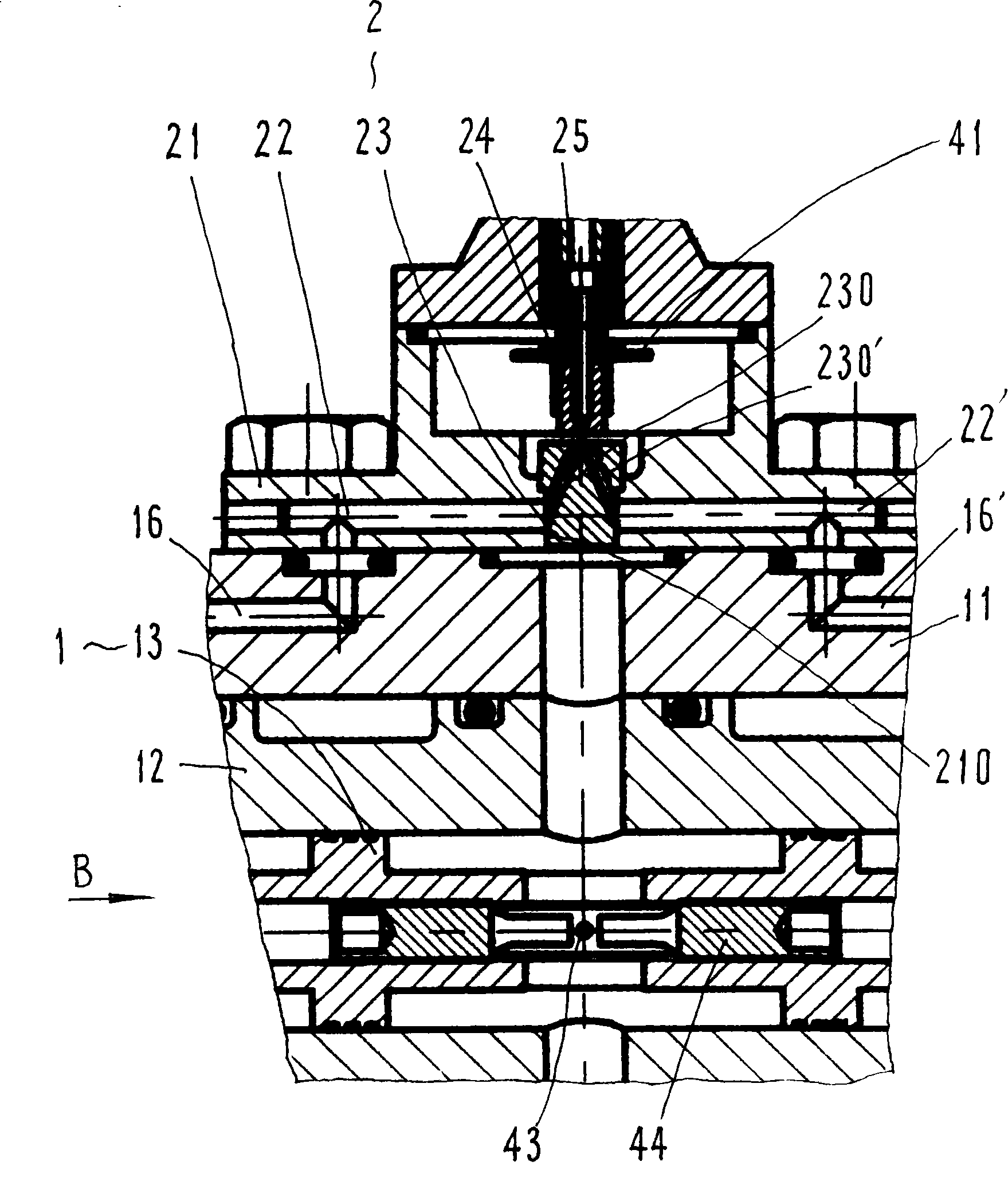
[0020] Main valve 1, its main structure is similar to existing products, main valve 1 includes valve body 11, valve sleeve 12, valve core 13, left and right control chamber 14, 14', left and right pressure block 15, 15' and Left and right guide holes 16, 16', wherein:

[0021] The valve body 11 is provided with left and right guide holes 16, 16' on the side adjacent to the fixed pre-stage jet tube 2; Road, the left and right guide holes 16, 16 'can...


PUM


Abstract

The invention relates to an electro-hydraulic servo valve for a prestage independent type jet flow pipe, which mainly solves the technical problems of the improvement of the manufacturability of the electro-hydraulic servo valve, and the like. The electro-hydraulic servo valve adopts the technical scheme that the prestage jet flow pipe is provided with a switching block; the bottom surface of theswitching block is connected with a main valve; the top surface of the switching block is connected with a torque motor; a receptor is fixed in an installing hole of the middle part of the switching block; a position adjacent to the bottom surface of the switching block is provided with a left oil hole and a right oil hole; one end of the left oil hole and one end of the right oil hole are connected with a left guide hole and a right hole of the main valve respectively; and the other end of the left oil hole and the other end of the right oil hole are communicated with a left receiving hole and a right receiving hole of the receptor respectively. The electro-hydraulic servo valve for the prestage independent type jet flow pipe is suitable for various electro-hydraulic servo valves for theprestage jet flow pipe.

Description

Technical field: [0001] The invention relates to a valve, in particular to a jet tube type two-stage electro-hydraulic servo valve. Background technique: [0002] The existing jet tube type force feedback two-stage electro-hydraulic servo valve includes a torque motor, a jet tube and a power stage main slide valve. The receiver is set on the valve sleeve of the main valve of the servo valve. When the hydraulic oil enters the servo valve, it enters the jet tube through the high-pressure oil pipe, and sprays to the two receiving holes on the receiver through the shrinking nozzle at the port of the jet tube. A receiving hole is connected to the long oil delivery hole opened on the valve sleeve, and the long hole introduces the received oil into both ends of the control valve core; when the torque motor has no control current input, the nozzle of the jet tube is in the middle position, and the two ends of the receiver The jet kinetic energy received by the receiving hole from t...

Claims


Application Information

Patent Timeline
Patent Type & Authority Patents(China)
IPC IPC(8): F16K11/07F16K31/12F16K37/00F16K27/00F16K17/26F15B13/02
Inventor 章敏莹渠立鹏李春龙方群
Owner SHANGHAI HENGTUO HYDRAULIC CONTROL TECH
Why Eureka
Try Eureka