
Method for producing a catalyst layer

A technology of catalytic layer and catalyst, applied in the field of catalytic layer, to achieve the effect of improving uniform distribution

Inactive Publication Date: 2013-02-27
ELCOMAX
View PDF2 Cites 0 Cited by
  • Summary
  • Abstract
  • Description
  • Claims
  • Application Information

AI Technical Summary

Problems solved by technology

[0006] In other words: The described electrochemical deposition method makes it possible to deposit expensive catalysts (e.g. platinum) only in those regions of the electrode layer or catalytic layer that require it later for energy conversion (or for chemical or electrochemical reactions)
Thus, significant advantages are obtained by electrochemical deposition compared to the conventional production of catalytic layers, especially for use in fuel cells, in which electrolysis and electrical contact cannot be brought about simultaneously or in a controlled manner to the desired extent.

Method used


Image

  • Method for producing a catalyst layer

Examples


Embodiment Construction

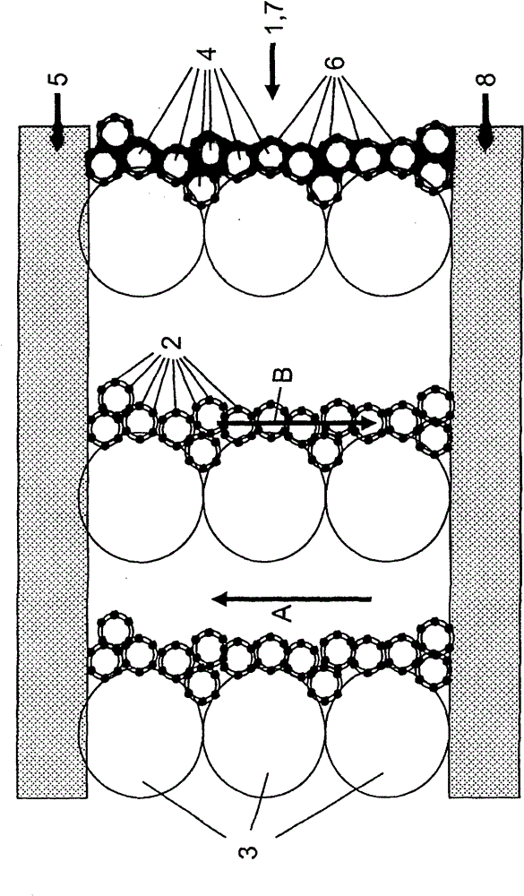
[0083] The catalyst layer 1 structured according to the invention contains many catalyst particles 2 of the order of 1.5 nm that are electrochemically deposited from a platinum salt, wherein, prior to the electrochemical deposition, larger conductive carbon particles 3 (average diameter of about 50 nm ) and smaller conductive carbon particles 4 (average diameter about 8 nm), applied to the gas diffusion layer used as the substrate by coating the precursor solution containing the particles 3, 4 on the substrate 5, and then press the precursor layer tightly on the substrate 5. Larger particles 3, which advantageously have a high graphite fraction and thus a hydrophobic surface, serve to form the coarse structure, while smaller particles here are impregnated with an electrolyte material 6 (here Nafion) and are thus almost completely covered by the electrolyte material 6 4 is used to form fine structures. Particles 3, 4 ensure the necessary electrical conductivity and constitute ...


PUM

PropertyMeasurementUnit
sizeaaaaaaaaaa
sizeaaaaaaaaaa
sizeaaaaaaaaaa

Abstract

A method for producing a catalyst layer (1) for fuel cells, chemical or electrochemical reactors using a precursor layer, which comprises a plurality of electrically conductive precursor particles (3, 4), a catalyst (2) being electrochemically deposited, the catalyst layer (1) being produced as a structured layer. This is achieved by the targeted inhomogeneous selection of the precursor particles (3, 4) with regard to at least one particle property, by the addition of non-conductive particles and / or at least one chemical additive to the precursor layer, and / or in that significant amounts of gas are produced in the catalyst layer or conveyed through said layer before, during, or after the electrochemical deposition.

Description

technical field [0001] The present invention relates to a method for producing catalytic layers for fuel cells, chemical or electrochemical reactors using a precursor layer containing a plurality of electrically conductive precursor particles, wherein the catalyst is electrochemically deposited. Furthermore, the invention relates to a catalytic layer produced according to the method and a precursor solution or precursor layer intended to be used within the framework of the method according to the invention. Background technique [0002] Such production methods and corresponding layers or solutions are known from EP 0 988 656 B1 or EP 1 307 939 B1, both of which are the subject of the disclosure in their entirety. The catalytic layer described in the above-mentioned publication is especially used as an integral part of the membrane electrode assembly (Membrane Electrode Assembly-MEA) necessary for the fuel cell. In order to describe the background of the present invention in ...

Claims


Application Information

Patent Timeline
Patent Type & Authority Patents(China)
IPC IPC(8): C25D5/54B01J21/18B01J37/34C25B9/10H01M4/88H01M4/90H01M4/92H01M4/96C25B9/23
CPCH01M8/0612C25D5/54B01J35/006H01M2008/1095B01J23/42B01J21/18B01J37/0248Y02E60/50B01J37/348B01J35/0033B01J35/393B01J35/33
Inventor 曼弗雷德·斯蒂芬纳
Owner ELCOMAX
Learn More