Gate dielectric layer, manufacturing method thereof, semiconductor device and manufacturing method thereof
A gate dielectric layer and manufacturing method technology, applied in the field of gate dielectric layer and its manufacturing, can solve the problems of inability to form semiconductor devices with different performances and inability to control nitrogen distribution
- Summary
- Abstract
- Description
- Claims
- Application Information
AI Technical Summary
Problems solved by technology
Method used
Image
Examples
Embodiment 1
[0055] Figure 4 to Figure 5 It is a schematic cross-sectional view of structures corresponding to each step of the manufacturing method of the first embodiment of the manufacturing method of the gate dielectric layer of the present invention.
[0056] Please refer to Figure 4 , firstly, a substrate 10 is provided, and a silicon oxide layer 12 is provided on the substrate 10 .
[0057] Wherein, the substrate 10 may be a semiconductor material, such as one of single crystal silicon, polycrystalline silicon or amorphous silicon, or may be a silicon on insulating layer (Silicon On Insulator, SOI) structure or an epitaxial layer structure on silicon. N-type impurities or P-type impurities may be doped into the substrate 10 .
[0058]The method for forming the silicon oxide layer 12 includes but not limited to high temperature furnace tube oxidation, rapid thermal annealing oxidation or in-situ steam generation oxidation (ISSG) process.
[0059] Before forming the silicon oxide...
Embodiment 2
[0073] Through one ion implantation and nitridation process, the nitrogen in the silicon oxide layer may not be able to achieve the desired distribution. In this embodiment, the ion implantation and nitridation process can be divided into multiple times. Optionally, in each ion implantation and nitridation process, the implantation energy or implantation dose is different, or the implantation energy and dose are both different, so as to form a silicon oxide layer with nitrogen concentration distribution meeting the requirements. I won't go into details here.
Embodiment 3
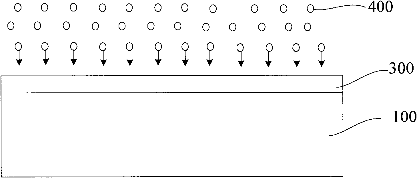
[0075] With the continuous improvement of the semiconductor manufacturing process, the thickness of the gate dielectric layer is getting thinner; correspondingly, when forming the gate dielectric layer of the nitrogen-containing silicon oxide layer, the thickness of the silicon oxide layer is also continuously thinning, for example, in At the 65nm technology node, the thickness of the silicon oxide layer is only 12A, and at 45nm, the thickness of the silicon oxide layer will be even thinner. For such a thin silicon oxide layer, when the ion implantation nitridation process is adopted, the implanted nitrogen ions may penetrate the silicon oxide layer, thereby affecting the film characteristics of the formed gate dielectric layer. In this embodiment, the problem of nitrogen ions penetrating the silicon oxide layer is improved by first forming a buffer layer on the silicon oxide layer to be doped.
[0076] Figure 6 to Figure 8 It is a schematic cross-sectional view of the struc...
PUM
 Abstract
Description
Claims
Application Information
 - R&D
- Intellectual Property
- Life Sciences
- Materials
- Tech Scout
- Unparalleled Data Quality
- Higher Quality Content
- 60% Fewer Hallucinations
Browse by: Latest US Patents, China's latest patents, Technical Efficacy Thesaurus, Application Domain, Technology Topic, Popular Technical Reports.
© 2025 PatSnap. All rights reserved.Legal|Privacy policy|Modern Slavery Act Transparency Statement|Sitemap|About US| Contact US: help@patsnap.com


