

Polarizing plate and liquid crystal display device using the same
A technology of liquid crystal display device and polarizer, which can be used in polarizing elements, applications, household appliances, etc., and can solve the problem of limitation of brightness improvement.
- Summary
- Abstract
- Description
- Claims
- Application Information
AI Technical Summary
Problems solved by technology
Method used
Image

Examples
Embodiment 1-1
[0656] A borosilicate glass (BK-7) substrate (φ100mm) with a thickness of 500 μm is placed in an electron beam evaporation device, and the volatile source uses aluminum with a purity of 99.999%. -5Under the conditions of Pa, deposition rate of 1 nm / sec, and deposition source-substrate distance of 25 cm, electron beam deposition of aluminum was performed from the normal direction of the substrate surface to form a metal layer with a film thickness of 100 nm. Next, except that oxygen gas was introduced into the system at 0.5 sccm, aluminum was evaporated under the same conditions to produce a laminate having a black layer made of aluminum oxide with a film thickness of 100 nm on the metal layer. Also, a product in which only an aluminum layer of 100 nm was formed was produced in the same manner. Absolute reflectances Ra and Rb were measured for each of the metal layer and the black layer, and the light extinction rate L was obtained. The results are shown in Table 1.
[0657] ...
Embodiment 1-2
[0671] A resin pattern was formed on the black layer by the same method as in Example 1 except that the following mold 2 was used as a mold.
[0672] "Mould 2"
[0673] Material: Nickel
[0674] Pitch: 130nm, Convex width: 70nm, Convex height: 200nm
[0675] Cross-sectional shape of the concave part: rectangular shape.
[0676] When the shape of the base material released from the mold was observed, it was confirmed that a resin layer having a linear resin pattern having a cross-sectional shape substantially inverting the shape of the mold as follows was formed.
[0677] "Resin pattern shape on black layer"
[0678] Pitch p: 130nm, width w: 60nm, height h: 198nm
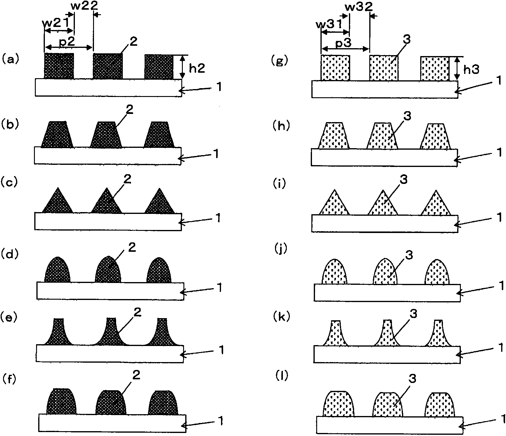
[0679] Next, samples were produced by the same method as in Example 1. The shape of the sample obtained by observation, the shape of the linear black layer and the linear metal layer is figure 2 The form shown in (a) is the dimension shown in Table 1.
[0680] Table 1 shows the obtained samples and the evalua...
Embodiment 1-3
[0682] A resin pattern was formed on the black layer by the same method as in Example 1 except that the following mold 3 was used as the mold.
[0683] "Mold 3"
[0684] Material: Nickel
[0685] Pitch: 120nm, Convex width: 65nm, Convex height: 120nm
[0686] Sectional shape of recessed part: Rectangular shape
[0687] When the shape of the base material released from the mold was observed, it was confirmed that a resin layer having a linear resin pattern having a cross-sectional shape substantially inverting the shape of the mold as follows was formed.
[0688] "Resin pattern shape on black layer"
[0689] Pitch p: 120nm, width w: 55nm, height h: 117nm
[0690] Next, samples were produced by the same method as in Example 1. The shape of the sample obtained by observation, the shape of the linear black layer and the linear metal layer are as follows: figure 2 The form shown in (a) is the dimension shown in Table 1.
[0691] Table 3 shows the obtained samples and the ev...
PUM
| Property | Measurement | Unit |
|---|---|---|
| width | aaaaa | aaaaa |
| thickness | aaaaa | aaaaa |
| thickness | aaaaa | aaaaa |
Abstract
Description
Claims
Application Information