High speed phase splitting circuit

A phase and circuit technology, applied in the field of integrated circuit design and optical communication, can solve the problems of two-way differential signal phase offset, common-mode voltage imbalance, multi-chip area, etc.

Inactive Publication Date: 2010-01-13
TIANJIN VAST TECH
View PDF0 Cites 12 Cited by
  • Summary
  • Abstract
  • Description
  • Claims
  • Application Information

AI Technical Summary

Problems solved by technology

However, this requires more chip area, and the response time of the low-pass filter will be longer
In this way, it often happens that the common-mode voltages at both ends of the phase-split amp...

Method used


Image

  • High speed phase splitting circuit
  • High speed phase splitting circuit
  • High speed phase splitting circuit

Examples


Embodiment Construction

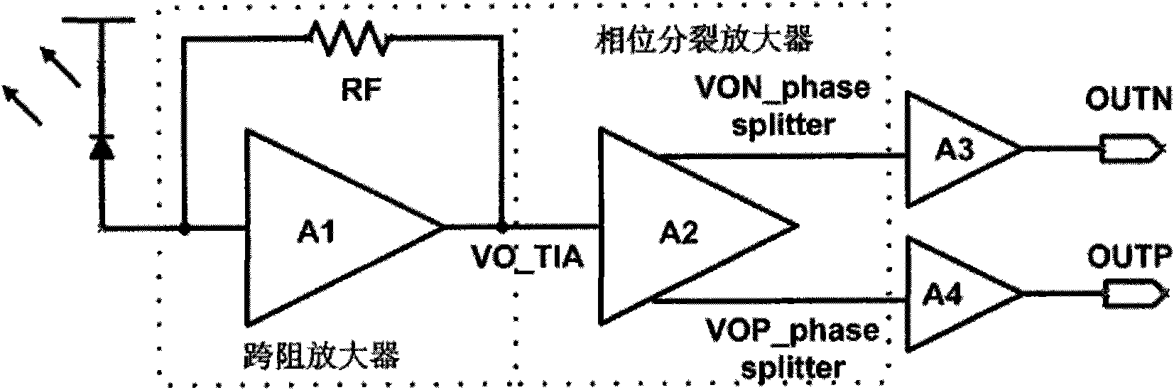
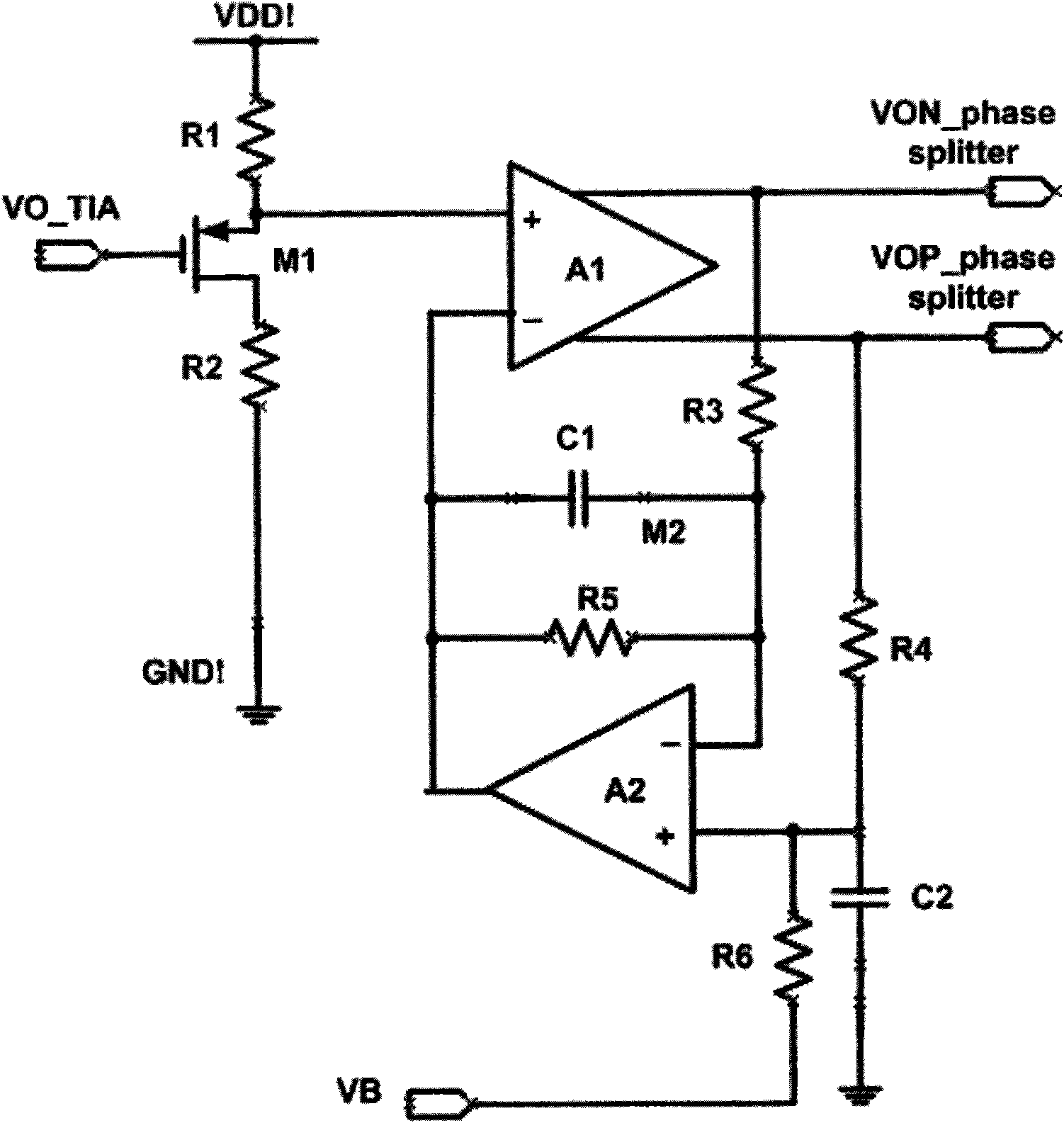
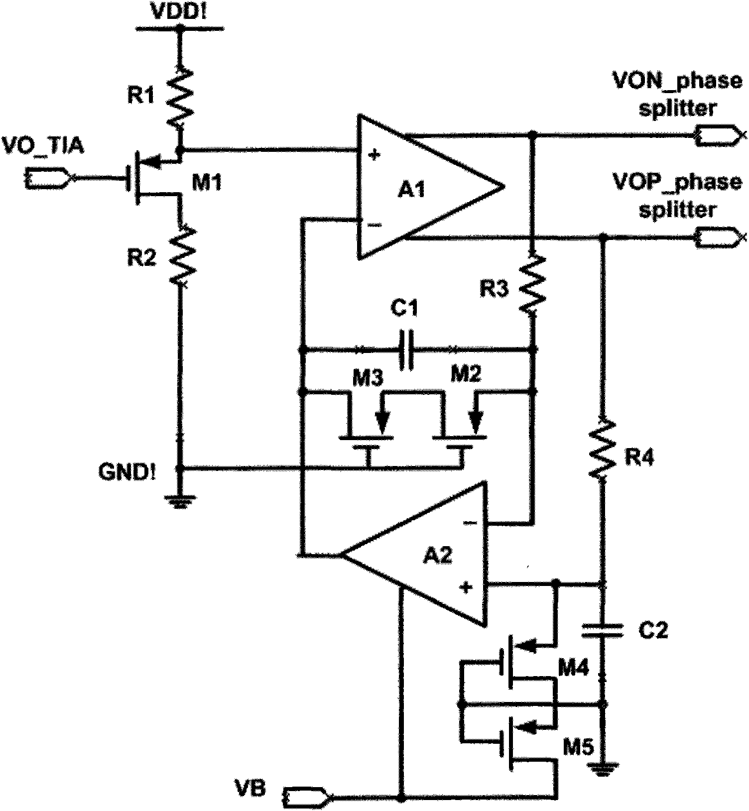
[0020] The present invention can be realized through the following technical solutions. The voltage signal output by the transimpedance amplifier is level-shifted by the source follower, and then input to the non-inverting input terminal of the phase splitting amplifier. The two-way output signal of the phase-split amplifier is not only output to the buffer circuit of the subsequent stage, but also output to the input end of the lossy integrator. The lossy integrator amplifies the voltage difference between the non-inverting and inverting input terminals, and adjusts the common-mode voltage at the inverting input terminal of the phase-splitting amplifier according to the amplification result. At low frequencies, the gain of the lossy integrator is determined by the resistor ratio to determine the common-mode value of the input voltage at the inverting terminal of the phase-splitting amplifier. At high frequencies, the integrating capacitor shorts the input to the output, so t...


PUM


Abstract

The invention is a high speed phase splitting circuit. In the circuit, a source follower is connected with a phase splitting amplifier which is connected with a lossy integrator; the source follower is used for carrying out level shift on the signal output by a transimpedance amplifier; the phase splitting amplifier is used for transforming the input single-ended signal into double-ended differential signal and amplifying the double-ended differential signal in a higher speed; two input ends of the lossy integrator are respectively connected with output ends of the phase splitting amplifier, and the common mode voltage difference of the phase splitting amplifier controls the output of the integrator; the output voltage of the integrator is connected on the reverse input end of the phase splitting amplifier, and the common mode voltage thereof changes with the common mode voltage of the input signal.

Description

technical field [0001] The invention belongs to the field of integrated circuit design in the field of optical communication, in particular to a high-speed phase splitting circuit. Background technique [0002] Fiber optic communication uses light as the information carrier and optical fiber as the transmission medium. At present, the bottleneck of the development of the optical communication industry. Microelectronic integrated circuits used in optical communication networks mainly include pre-transimpedance amplifiers, limiting amplifiers, clock and data recovery circuits, splitters and multiplexers, etc. The pre-transimpedance amplifier is directly connected to the photodetector device, and the photodetector device converts the input optical signal into a current, and the current signal is amplified by the preamplifier to obtain a corresponding voltage signal. Generally, the pre-transimpedance amplifier is single-ended, and needs to pass through a phase-splitting amplif...

Claims


Application Information

Patent Timeline
IPC IPC(8): H03K19/0175H03F3/16
Inventor 李景虎王永生喻明艳
Owner TIANJIN VAST TECH
Why Eureka
Try Eureka