Heat dissipating device for cooling machine cabinet

A heat dissipation device and cabinet technology, which is applied in the direction of cooling/ventilation/heating transformation, etc., can solve the problems that the cabinet heat dissipation device occupies a large space, has low heat dissipation effect, and cannot be processed, so as to shorten the working process, save energy consumption, and shorten the path Effect

Active Publication Date: 2010-01-13
DAWNING INFORMATION IND BEIJING +1
View PDF0 Cites 22 Cited by
  • Summary
  • Abstract
  • Description
  • Claims
  • Application Information

AI Technical Summary

Problems solved by technology

[0007] In order to solve the inconvenience of adjustment caused by the integration of the cabinet and the cooling device, it cannot be dealt with

Method used


Image

  • Heat dissipating device for cooling machine cabinet
  • Heat dissipating device for cooling machine cabinet
  • Heat dissipating device for cooling machine cabinet

Examples


Embodiment 1

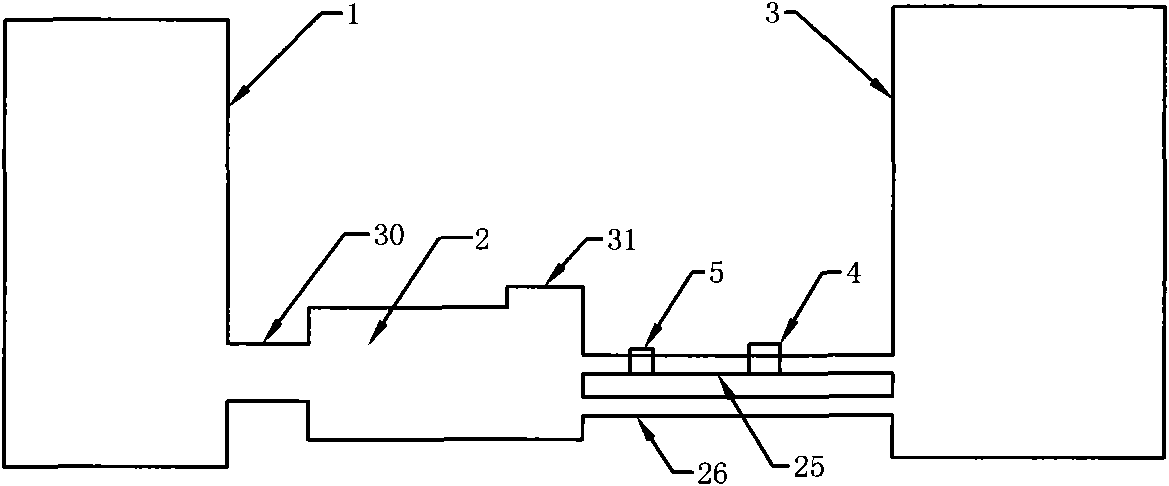
[0027] Such as figure 1 As shown, the heat dissipation device of the technical solution of the present invention includes an outdoor refrigeration unit 3 , a hot air suction device 1 , a water cooling circulation device 2 and a circulation pipeline, and the circulation pipeline includes a water inlet pipe 25 and a water outlet pipe 26 .

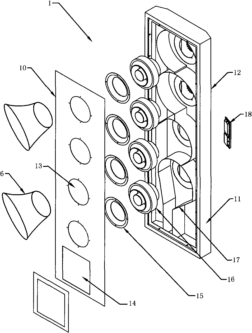
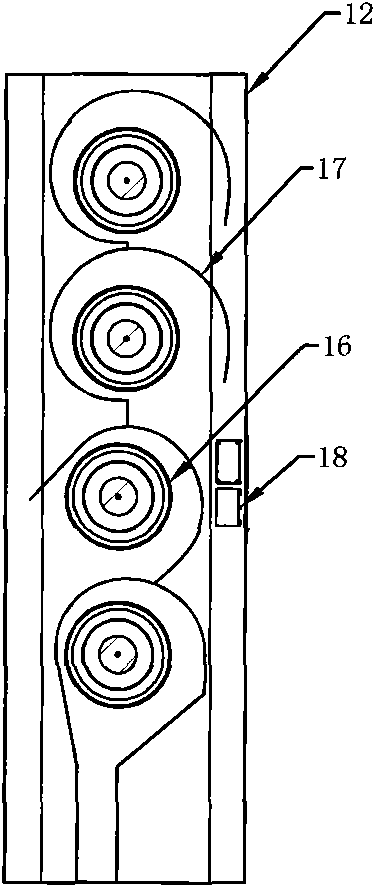
[0028] Such as figure 2As shown, the hot air suction device 1 adopts a box-shaped structure, including a front sealing plate 10, a frame 11, and a rear sealing plate 12. After the front and rear plates and the frame are closed, the device is integrally sealed. The air inlet 13, of course, the position of the air inlet does not have to be fixed on the central axis, it can be opened at any position of the box body in terms of the setting of the air suction and the internal air duct, and the number of air inlets also depends It can be increased or decreased according to actual needs. A suction fan 16 is installed inside the box, and the posit...

Embodiment 2

[0039] Such as figure 2 As shown, on the basis of Embodiment 1, the technical solution is also equipped with a suction ring 6 at the suction port 13, and the suction ring extends outward to align with the heat source, and the suction ring 6 can be folded to buckle on the heat source, so that The wind force of the suction fan can directly suck away the high temperature generated by the heat source, instead of absorbing it after it is dissipated.

Embodiment 3

[0041] On the basis of Embodiment 1, this technical solution can install multiple suction fans 16 in the same air suction port 13 to adapt to heat sources at the same height and different positions, so that each heat source has a corresponding suction fan to work.


PUM


Abstract

The invention relates to a heat dissipating device for cooling a machine cabinet, in particular to a heat dissipating device adopting air-water exchanging refrigeration. A hot-air suction device is in a box-shaped stereostructure, an air inlet and an air outlet are arranged on the surface of a box body, a monitoring module is arranged in the box body, suction fans are installed on a position in the box body corresponding to the air inlet, and each suction fan is connected with the air outlet through an air channel; the scheme has a short heat dissipating path, shortens a working process, and further improves the heat dissipating efficiency of heat dissipating space; and each suction fan is connected with the air outlet through a single channel, the air entering one fan does not influence the air entering any other fans, the number and the revolutions of the suction fans doing work can be adjusted according to the temperature of the heat dissipating space, and the whole circulation process is controlled by a monitoring system. The scheme adopts partial redundancy design or total redundancy design, and all the operation can be switched onto a standby system when a main water coolingsystem has a fault, so as to ensure the normal running of the water cooling system, thereby maximizing the efficiency. The scheme has a short refrigeration path and strong pertinency, and can achievethe efficiency maximization.

Description

technical field [0001] The invention relates to a heat dissipation device, in particular to a device for cooling blade server cabinets by exchanging wind and water for cooling. Background technique [0002] Nowadays, our life is entering an information age where the electronic industry is booming. Various high-tech products and electronic equipment derived from computers are developing rapidly, bringing great convenience to people's daily life. However, with the current The continuous research and development and improvement of various electronic technologies, and the research and development concept of related electronic products are based on the data processing mode of high frequency and high speed, and the main axis of development is light, thin, short and small appearance. After the casing shrinks, the size of the internal chip will gradually change towards miniaturization and integration. This design concept causes the heat density of electronic components to become hig...

Claims


Application Information

Patent Timeline
IPC IPC(8): H05K7/20
Inventor 历军李宁李程童中原冯瑞军
Owner DAWNING INFORMATION IND BEIJING
Why Eureka
Try Eureka