
Integral high frequency rectifying device

A high-frequency rectification and high-frequency transformer technology, applied in the field of power supply, can solve the problems of overheating of surrounding conductors, easy to burn rectifier tubes, failures at the connection, etc., and achieve the effects of reliable performance, good cooling effect, and improved heat dissipation effect.

Inactive Publication Date: 2010-01-20
石新春
View PDF0 Cites 11 Cited by
  • Summary
  • Abstract
  • Description
  • Claims
  • Application Information

AI Technical Summary

Problems solved by technology

Existing high-frequency transformers generally require ring-shaped iron cores made of ferrite, microcrystalline or amorphous iron core materials, and special multi-strand wires are used for the wires. The disadvantage of this structure is that it is difficult for the transformer to dissipate heat. It is made into a high-power device, and the high-frequency transformer has a large leakage inductance, which causes a high switching overvoltage when the high-frequency switching tube is switched, which easily burns the rectifier tube and reduces the reliability of the large-capacity rectifier device.
In addition, the existence of medium frequency induction and high frequency induction will cause overheating of conductors around the lead-out wires of high-power high-frequency transformers, resulting in frequent failures at the connection between existing high-frequency transformers and high-frequency rectifiers

Method used


Image

  • Integral high frequency rectifying device
  • Integral high frequency rectifying device
  • Integral high frequency rectifying device

Examples


Embodiment Construction

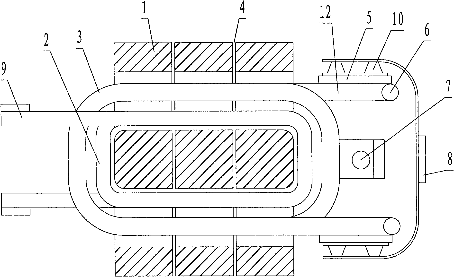
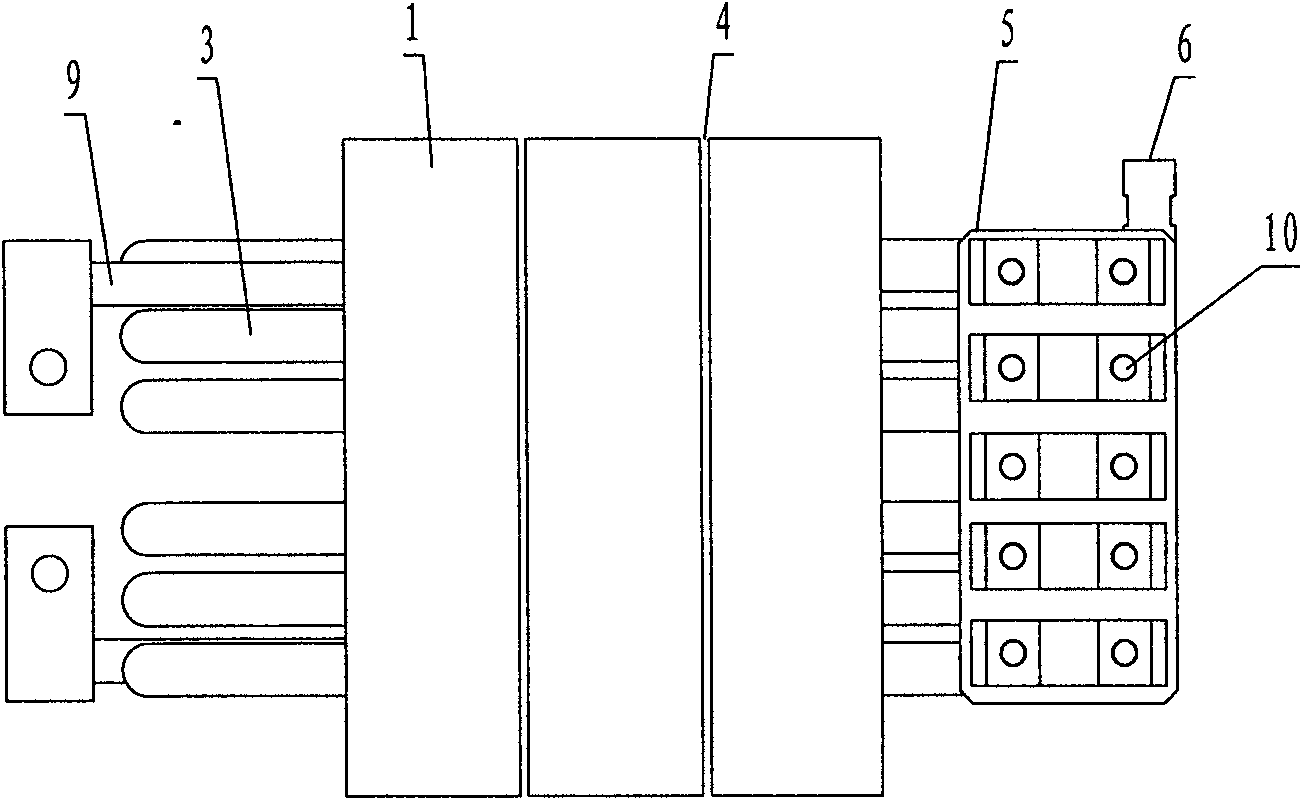
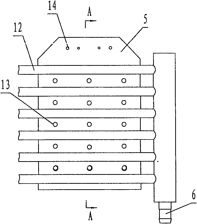
[0023] see Figure 1 ~ Figure 2 , the present invention combines the high-frequency transformer and the high-frequency rectifier together, and adopts the DC bus copper bar to lead out after the rectification, so there is no leakage inductance of the high-current lead wire of the high-frequency transformer and additional heating problems caused by high-frequency induction.

[0024] In order to solve the problem of high-power and high-current winding, the primary winding 2 and secondary winding 3 of the high-frequency transformer are made of copper or aluminum tubes, and the thickness of the tube wall is directly related to the frequency of the high-frequency inverter. Considering the skin effect and making full use of the conductor cross section. The primary winding of the high-frequency transformer is wound in series with 2 turns, and the secondary winding 3 is wound in parallel. The end of the coil is welded to the cooling plate 5 of the high-frequency rectifier. The interior...


PUM


Abstract

The invention relates to an integral high frequency rectifying device used for solving the problems of heat dissipation and inductance leakage of a high power DC power supply. The technical proposal comprises: the rectifying device comprises a high frequency transformer and a high frequency rectifier, wherein the high frequency transformer consists of an iron core, a primary winding and a secondary winding; the secondary winding is formed by connecting a plurality of winding units with the same structure in parallel, and each winding unit has two turns, the middle point of which is connected with an output cathode copper bar, and the two ends thereof are connected with an output anode copper bar by the high frequency rectifier; the high frequency rectifier comprises a diode and a heat dissipation plate, wherein one end of the diode is fixed on the heat dissipation plate, and the other end thereof is connected with the output anode copper bar; the heat dissipation plate is directly and fixedly connected with a metal tube extracted out of the secondary winding. The windings of the rectifying device are wound by the metal tubes and are internally filled with cooling medium, so as to not only have good heat dissipation effect, but also fully utilize the section of a conductor under the condition of very strong skin effect; therefore, the integral high frequency rectifying device is especially suitable for manufacturing the high power switch-type DC power supply.

Description

technical field [0001] The invention relates to a high-power high-frequency switch-type DC power supply, which belongs to the technical field of power supplies. Background technique [0002] With the continuous advancement of technology and the continuous deepening of research, the power of high-frequency switching power supply is getting bigger and bigger, but there are many factors that restrict the increase of switching power supply capacity. Only by continuously improving the structure of high-frequency switching power supply can we overcome various problems. Unfavorable factors make the switching power supply develop in the direction of higher power. [0003] Switching DC power supply usually adopts double conversion method, that is, the grid power supply is first rectified into DC power, then converted into high-frequency AC power through an inverter, then transformed and isolated by a high-frequency transformer, and finally output DC power through high-frequency recti...

Claims


Application Information

Patent Timeline
Patent Type & Authority Applications(China)
IPC IPC(8): H02M7/02H05K7/20H01F27/28H01F27/24H01F27/08
Inventor 石新春
Owner 石新春
Learn More