Sputtering target material and sputtering target obtained by using the sputtering target material

A sputtering target and sputtering target technology, applied in the field of sputtering targets, can solve the problems of reducing arcs, unable to fully suppress target cracks and cracks, etc., so as to reduce the generation of arcs and inhibit the generation of cracks or cracks. , the effect of improving utilization efficiency

Active Publication Date: 2010-01-20
MITSUI MINING & SMELTING CO LTD
View PDF3 Cites 11 Cited by
  • Summary
  • Abstract
  • Description
  • Claims
  • Application Information

AI Technical Summary

Problems solved by technology

However, although these targets have some improvement effects, they are still not products that can reliably reduce arc generation.
Furthermore, when these targets are produced, cracks in the target and generation of cracks cannot be sufficiently suppressed.

Method used


Image

  • Sputtering target material and sputtering target obtained by using the sputtering target material
  • Sputtering target material and sputtering target obtained by using the sputtering target material
  • Sputtering target material and sputtering target obtained by using the sputtering target material

Examples


Embodiment 1

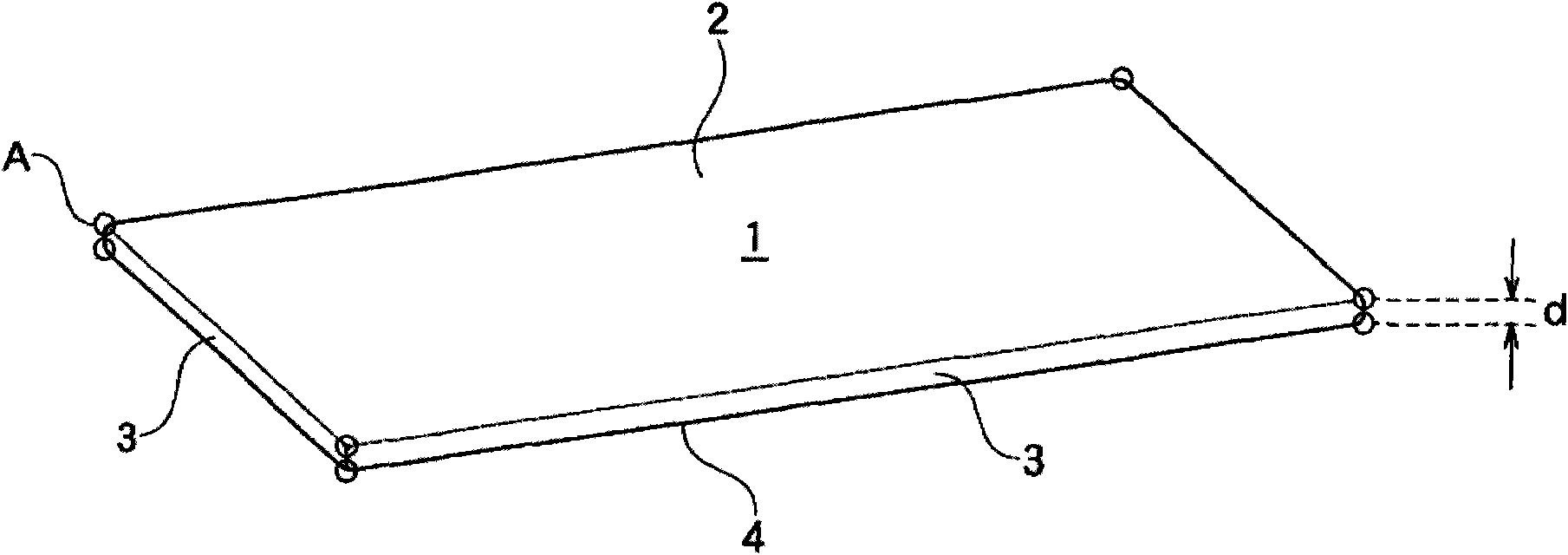
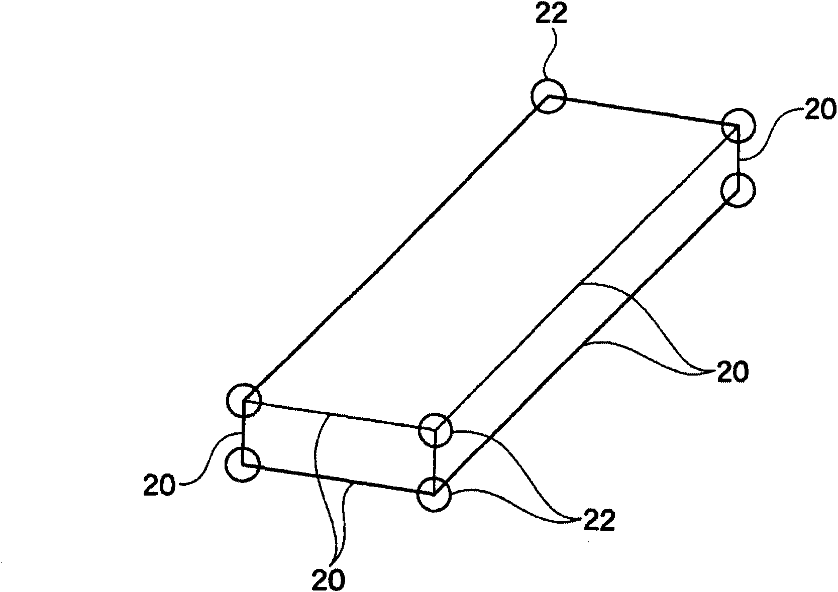
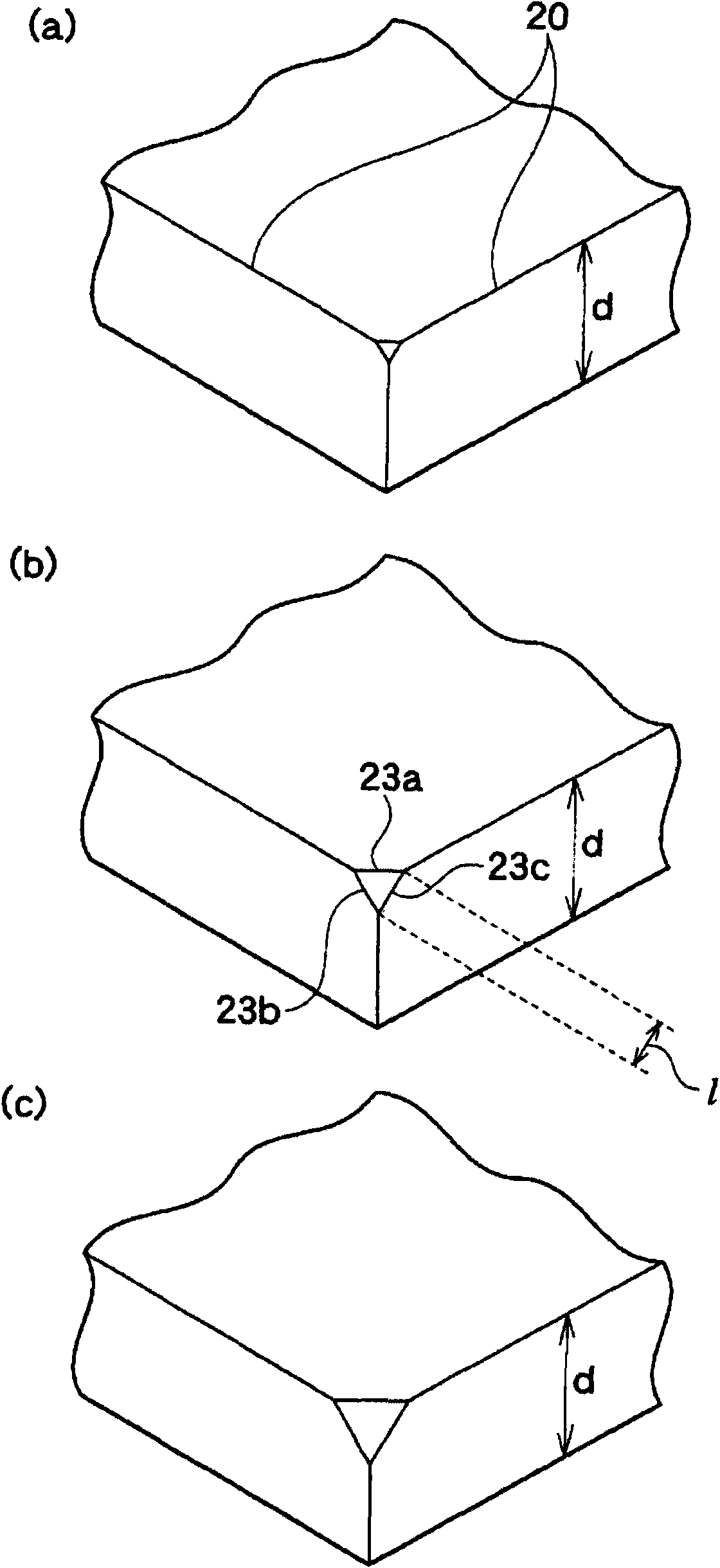
[0114] Such as Figure 6 As shown, a nearly plate-shaped ITO sputtering target (SnO 2 =10% by weight, the relative density is 99.8%), the chamfering treatment of R1 was performed on the edge parts 45a-45c, and the chamfering treatment of R1 was performed on the four corners A located on the sputtering surface 2.

[0115] Then, this sputtering target 1 was bonded to a back plate (230×750×20 mm) made of oxygen-free copper using the above-mentioned adhesive material, thereby producing a sputtering target. Using the obtained sputtering target, evaluation was performed on each of the evaluation items described above. The obtained results are shown in Table 1.

Embodiment 2

[0120] The ITO sputtering target composed of the materials shown in Table 1 was manufactured, and the chamfering treatment of C0.3 was implemented on the four corners A of the sputtering surface 2, and the edges and corners of the bonding surface were C0.5 chamfering treatment is implemented on the part.

[0121] Then, in the same manner as in Example 1, a sputtering target was produced, and various evaluations were performed. The obtained results are shown in Table 1.

Embodiment 3~9、 comparative example 3~5

[0126] ITO sputtering targets composed of the materials shown in Table 1 were manufactured, and chamfering was performed on the edges or corners according to the contents shown in Table 1.

[0127] Then, in the same manner as in Example 1, a sputtering target was produced, and various evaluations were performed. The obtained results are shown in Table 1.


PUM


Abstract

Provided are a sputtering target material by which generation of arcing can be surely reduced and generation of breakage and cracks is suppressed, and a sputtering target obtained by using the sputtering target material. The substantially board-like sputtering target material has a rectangular sputtering surface, rectangular side surfaces and a rectangular bonding surface. A corner section, which is formed by having at least three surfaces abut to each other among a plurality of surfaces constituting the sputtering target material, is chamfered.

Description

technical field [0001] The present invention relates to a sputtering target material characterized in that a corner portion is chamfered, and a sputtering target obtained from the sputtering target material. Background technique [0002] Hitherto, as a film-forming method used in the production of materials for electronic devices such as semiconductors and materials for electrical devices, sputtering, which allows relatively easy control of film thickness and composition, has been widely used. The sputtering target used in this sputtering method generally adopts the following sputtering target, that is, a sputtering target composed of a material to be formed into a thin film through an adhesive material, and a sputtering target made of a material having excellent electrical conductivity and thermal conductivity. The backplane composed of materials is bonded together. [0003] When performing a sputtering process using a sputtering target, it is desired to reduce arc generat...

Claims


Application Information

Patent Timeline
IPC IPC(8): C23C14/34
CPCC23C14/34H01J37/3491C23C14/3407C23C14/086
Inventor 松前和男
Owner MITSUI MINING & SMELTING CO LTD
Why Eureka
Try Eureka