Sputtering target material and sputtering target obtained by using the sputtering target material

A sputtering target and sputtering target technology, applied in the field of sputtering targets, can solve the problems of reducing arcs, unable to fully suppress target cracks and cracks, etc., so as to reduce the generation of arcs and inhibit the generation of cracks or cracks. , the effect of preventing rupture

Active Publication Date: 2012-03-21
MITSUI MINING & SMELTING CO LTD
View PDF2 Cites 0 Cited by
  • Summary
  • Abstract
  • Description
  • Claims
  • Application Information

AI Technical Summary

Problems solved by technology

However, although these targets have some improvement effects, they are still not products that can reliably reduce arc generation.
Furthermore, when these targets are produced, cracks in the target and generation of cracks cannot be sufficiently suppressed.

Method used


Image

  • Sputtering target material and sputtering target obtained by using the sputtering target material
  • Sputtering target material and sputtering target obtained by using the sputtering target material
  • Sputtering target material and sputtering target obtained by using the sputtering target material

Examples


Embodiment

[0060] Hereinafter, the present invention will be specifically described based on examples, but the present invention is not limited by these examples.

[0061] In addition, evaluation was performed according to the following evaluation items using the obtained sputtering target.

[0062] > The obtained sputtering target material was bonded (bonded) to a back plate made of oxygen-free copper using a bonding material (pure In). This sputtering target material was peeled off from a backing plate, and it bonded again using the adhesive material (pure In). After repeating this bonding ten times, it was checked whether or not a chip was formed on the sputtering target. ◯: Notch was not generated at all in the entire edge portion of the adhesive surface. Δ: 1 to 3 chippings occurred in all the edge portions of the bonding surface. ×: Four or more chippings occurred in all the edge portions of the adhesive surface.

[0063] > During the folding process, packaging process, or load...

Embodiment 2

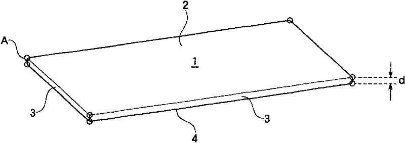
[0070] [Example 2] An ITO sputtering target composed of the materials shown in Table 1 was manufactured, and C0.3 chamfering treatment was implemented on the four corners A of the sputtering surface 2, and on the bonding surface C0.5 chamfering is applied to the edges and corners.

[0071] Then, in the same manner as in Example 1, a sputtering target was produced, and various evaluations were performed. The obtained results are shown in Table 1.

Embodiment 10

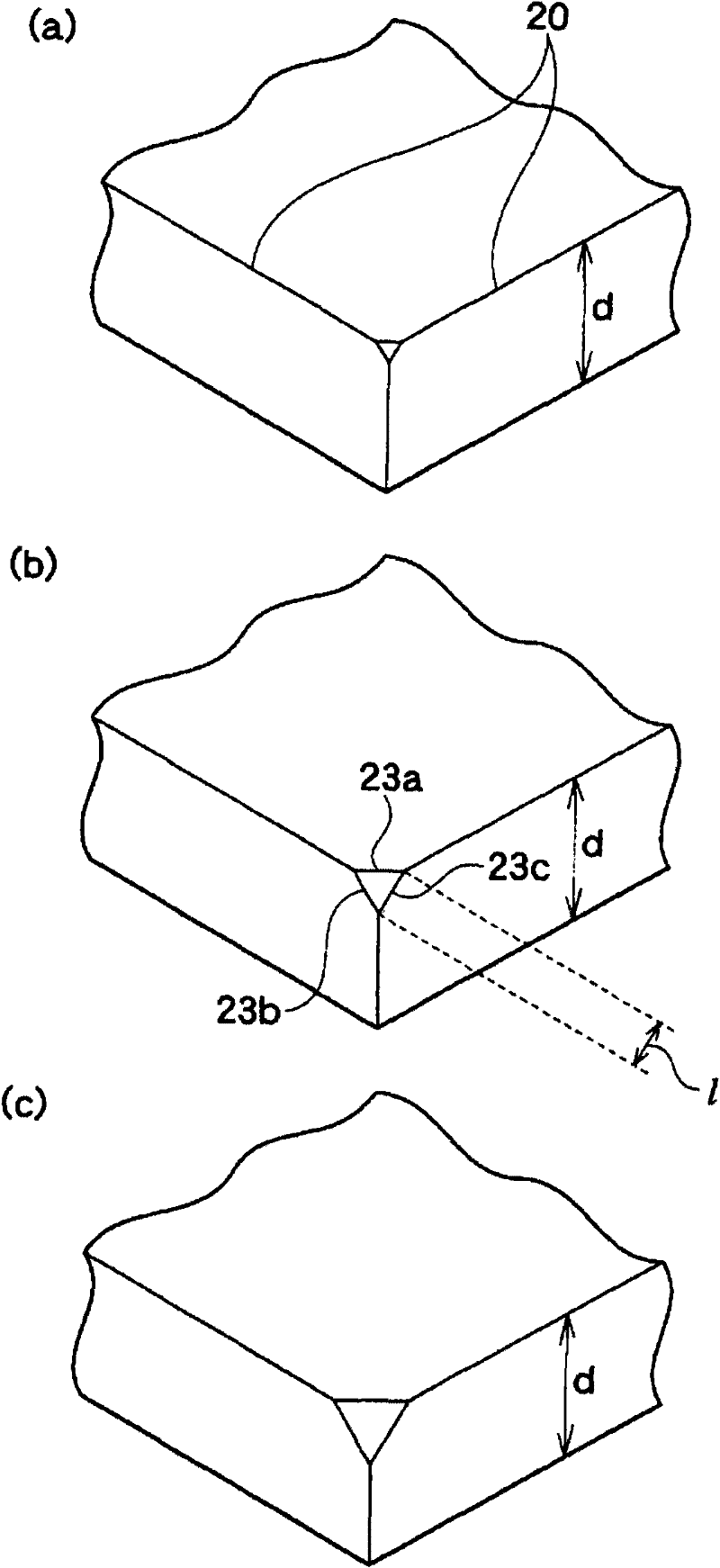
[0076] [embodiment 10] two wide 150mm * long 635mm * thick 10mm approximate plate-shaped ITO sputtering targets (SnO 2 =10% by weight, the relative density is 99.7%), R1 chamfering treatment was performed on the edge parts 45a-45c, and C3 chamfering treatment was performed on the edge part and corner part located on the bonding surface.

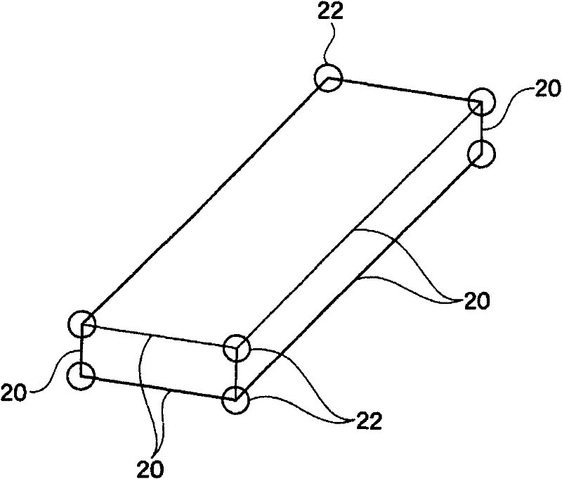
[0077] Then, these two sputtering targets were bonded to the back plate using the above-mentioned adhesive material, thereby producing a multi-segmented sputtering target in which the two sputtering targets were arranged side by side. The two sputtering targets were arranged such that their respective long sides were aligned in parallel with an interval of 0.3 mm. With respect to the sputtering surface, the chamfering process of R1 was given to the corner part B, and the chamfering process was also given to the corner part A located in the divided part where two sputtering targets oppose each other. Using the obtained multi-split sputtering ...


PUM


Abstract

Provided are a sputtering target material by which generation of arcing can be surely reduced and generation of breakage and cracks is suppressed, and a sputtering target obtained by using the sputtering target material. The substantially board-like sputtering target material has a rectangular sputtering surface, rectangular side surfaces and a rectangular bonding surface. A corner section, whichis formed by having at least three surfaces abut to each other among a plurality of surfaces constituting the sputtering target material, is chamfered.

Description

technical field [0001] The present invention relates to a sputtering target material characterized in that a corner portion is chamfered, and a sputtering target obtained from the sputtering target material. Background technique [0002] Hitherto, as a film-forming method used in the production of materials for electronic devices such as semiconductors and materials for electrical devices, sputtering, which allows relatively easy control of film thickness and composition, has been widely used. The sputtering target used in this sputtering method generally adopts the following sputtering target, that is, a sputtering target composed of a material to be formed into a thin film through an adhesive material, and a sputtering target made of a material having excellent electrical conductivity and thermal conductivity. The backplane composed of materials is bonded together. [0003] When performing a sputtering process using a sputtering target, it is desired to reduce arc generat...

Claims


Application Information

Patent Timeline
Patent Type & Authority Patents(China)
IPC IPC(8): C23C14/34
CPCC23C14/34C23C14/3407H01J37/3491C23C14/086
Inventor 松前和男
Owner MITSUI MINING & SMELTING CO LTD
Why Eureka
Try Eureka