
Ball dropper used for drop ball forming of oxide

A technology of oxide and ball dropper, which is applied in the direction of chemical instruments and methods, chemical/physical processes, liquid separation into beads and granulation, etc. It can solve the inconvenience of disassembly and cleaning, sticking of drippers, uneven particle size of formed products, etc. problems, to achieve the effect of regular shape and uniform size

Active Publication Date: 2010-01-27
CHINA PETROLEUM & CHEM CORP +1
View PDF1 Cites 22 Cited by
  • Summary
  • Abstract
  • Description
  • Claims
  • Application Information

AI Technical Summary

Problems solved by technology

These types of dripping ball devices have their own advantages and disadvantages. The (1) and (2) types of dripping ball devices all have defects such as uneven particle size of the formed product, complex structure of the device, and difficulties in processing and maintenance. The (3) type The drip ball device is usually a "shower pod"-shaped shell with a drip head, which remains static during the production process, mainly relying on controlling the applied pressure of the slurry in the drip ball tray and the inner diameter of the drip head to control the drip ball rate and the particle size of the ball
Compared with the first two drip ball trays, the (3) drip ball tray has the characteristics of simple device structure and low manufacturing cost, but has the disadvantages of inconvenient disassembly and cleaning
[0004] When the above three dripping devices are used in conjunction with the oil ammonia column to produce small balls, the dripper is directly exposed to the production environment, and it is easy to contact with the ammonia gas that volatilizes from the oil ammonia column into the environment, and the dripper is prone to "sticking". And clogging and other phenomena, the roundness of the product particles is low, and it is easy to produce "joint ball" particles
This not only seriously affects the continuous and large-scale production of spherical catalysts or supports, but also reduces product quality

Method used


Image

  • Ball dropper used for drop ball forming of oxide
  • Ball dropper used for drop ball forming of oxide
  • Ball dropper used for drop ball forming of oxide

Examples


example 1

[0034] Alumina pellets are produced by adopting the dropping ball device provided by the invention and the oil ammonia column forming method.

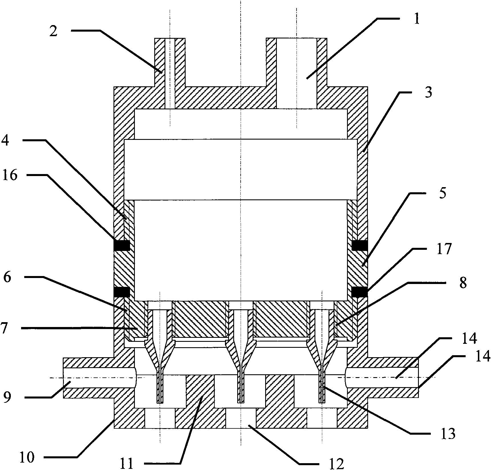
[0035] use the present invention figure 1 The drip bulb shown in the figure, but 10 dripper sockets are evenly arranged on the bottom plate of the lower housing of the dripper, and 10 drippers are installed, and the distance between the drippers is 25 mm. The gas disturbance plate is installed on the bottom plate of the jacket of the ball dropper, and the angle α between them is 120°. The diameter of the dropper of the dripper is 1 mm, and there are 10 vents with a diameter of 30 mm on the bottom plate of the dripper jacket. Each vent corresponds to a dripper and is coaxial with the dripper.

[0036] The oily ammonia column is 1.5 meters high and 7 centimeters in column diameter, n-heptane is the oil phase, its viscosity is 0.41 centipoise, the oil layer is 2 millimeters high, and 8 mass % ammonia water is the water phase with a heigh...

example 2

[0041] The zirconia-silicon oxide pellets are produced by adopting the dropping ball device provided by the invention and the oil ammonia column forming method.

[0042] use Figure 5 The difference in the drip bulb shown is that 200 drippers are installed on the bottom plate of the lower housing of the drip bulb, and the 200 drippers are evenly distributed on the bottom plate of the lower housing of the drip bulb, and the distance between the drippers is 30 mm. There are 210 ventilation openings with a diameter of 35 mm on the bottom plate of the dropper jacket, of which 200 ventilation openings correspond to a dripper and are coaxial with the dripper. The gas turbulence components on the base plate are gas pipelines with gas outlets distributed in the air vents in the jacket. The drip-tip has a diameter of 2 mm and protrudes 2 mm from the bottom of the bulb lower housing.

[0043] Continuously produce zirconia-silica pellets with zirconium hydroxide colloid and silica sol ...

example 3

[0049] Adopt the dripping ball device of example 2 and the oleyl ammonia column to produce ZSM-5-alumina pellets. The difference is that the bottom of the drop ball device is 10 cm away from the oil surface.

[0050] The ZSM-5-alumina pellets are continuously produced from the mixture of aluminum hydroxide colloid and ZSM-5 powder. The solid content of aluminum hydroxide colloid in the raw material is 30% by mass, the silicon oxide / alumina molar ratio of the ZSM-5 powder is 60, and the mass of aluminum hydroxide and ZSM-5 is 1:1.

[0051] Drop rate is 20 drops / cm 2 ·minute. The protective gas in the jacket of the dropper is air, the flow rate is 30 ml / min, and the pressure is 0.12 MPa.

[0052] The raw material slurry and air intermittently enter the shell of the ball dropper. After the particles of the raw material slurry drop out, they form balls in the oil phase of the oil ammonia column. The balls pass through the oil-ammonia water interface smoothly, enter the ammonia ...


PUM

PropertyMeasurementUnit
Particle sizeaaaaaaaaaa

Abstract

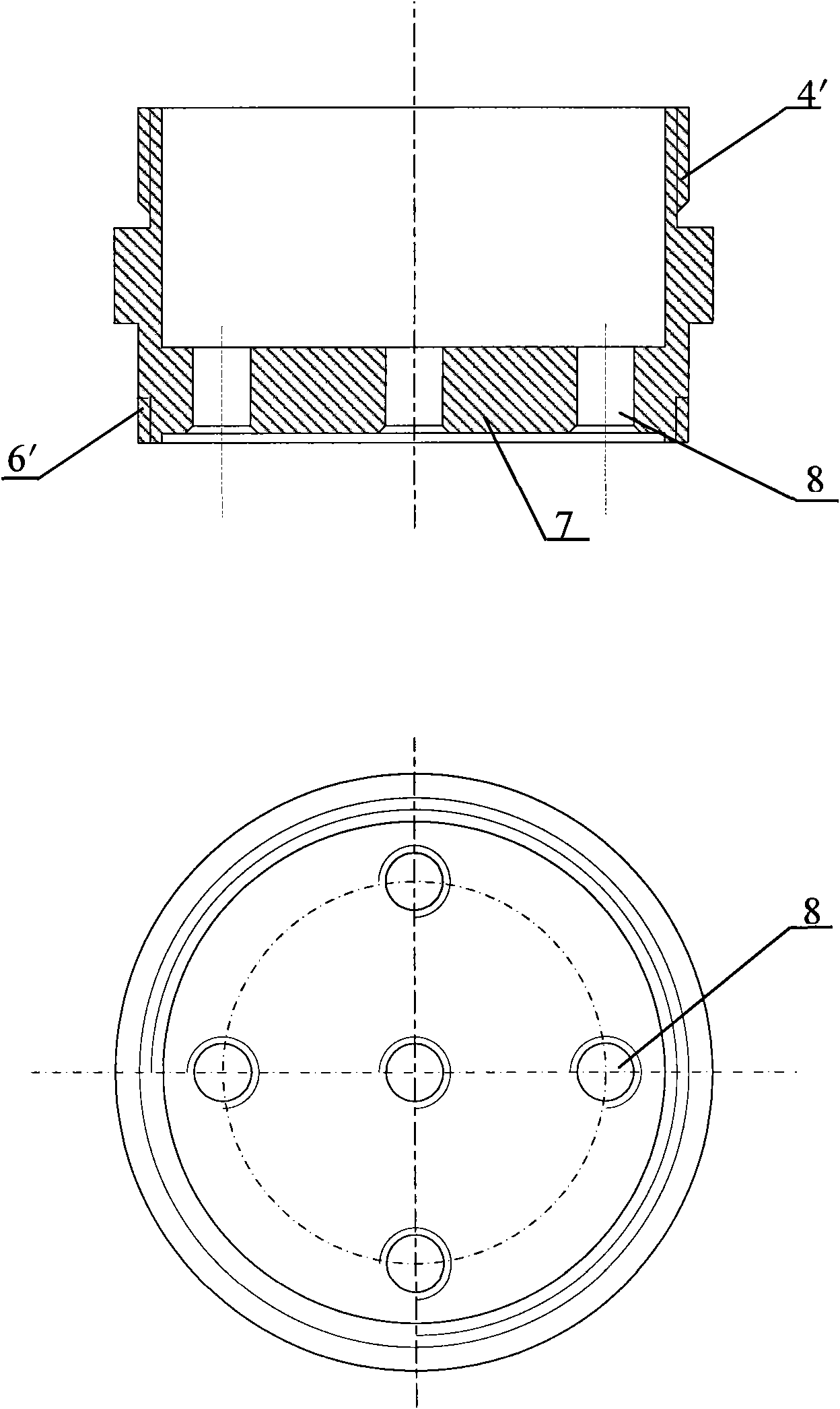
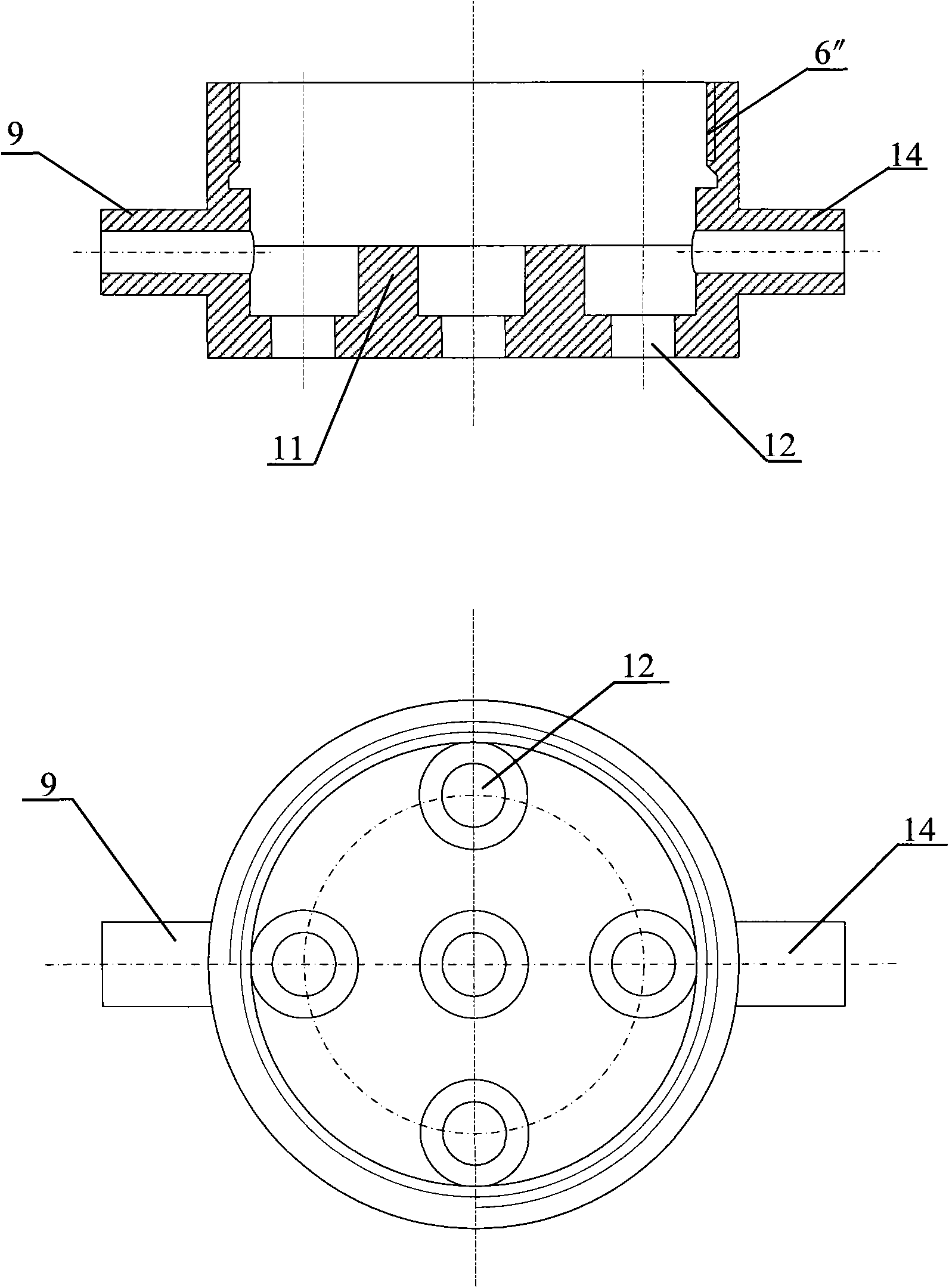
The invention discloses a ball dropper used for drop ball forming of oxide, which comprises a ball dropper shell and a ball dropper jacket (10). The upper part of the ball dropper shell is provided with an air inlet (2) and a material inlet (1), a bottom plate (7) of the shell is provided with a drop head jack (8), a drop head (13) is fixed in the drop head jack, the ball dropper jacket (10) is positioned at the lower part of the ball dropper shell, the lower end of the drop head (13) is extended into the jacket (10) to correspond to a ventilation opening (12) formed on the bottom plate of the ball dropper jacket, and the middle part of the wall of the ball dropper jacket (10) is provided with a gas inlet (9) and a gas outlet (14). The ball dropper is matched with an oil-ammonia column and used for the drop ball forming of the oxide, and can avoid the phenomenon of adhesion and ball connection produced by contact of wet balls and ammonia gas so that the solidified ball has good shape roundness and uniform size.

Description

technical field [0001] The invention relates to a solid slurry drop ball forming device, in particular to a drop ball forming device for oxide drop balls. Background technique [0002] The oily ammonia column forming method is an important method for producing spherical catalysts or carriers. In this method, the raw material slurry or sol is formed into small balls through a ball dropper. The small balls are dropped into the oily ammonia column under the action of gravity to solidify and age. Drying and calcining form spherical catalyst or carrier. The dropper is an important equipment in the production process, and it is one of the important factors to determine the quality and output of catalyst or carrier pellets. [0003] The drop ball device used in the oil ammonia column forming method mainly includes: (1) the drop ball device for the linear reciprocating motion of the drop ball plate; (2) the drop ball device for the uniform rotation of the drop ball plate; (3) the d...

Claims


Application Information

Patent Timeline
IPC IPC(8): B01J2/04B01J35/08
Inventor 马爱增潘锦程王国成张昕
Owner CHINA PETROLEUM & CHEM CORP
Learn More