Heat radiation device of heat pipe of loop of temperature-equalization tank with high heat conductivity

A technology of loop heat pipe and heat dissipation device, which is applied to the cooling/heating device, lighting device, indirect heat exchanger, etc. of lighting device, can solve the problems of difficult to balance the temperature at the heat source, affecting the conduction of heat, and the existence of voids, etc. Achieve the effect of improving LED luminous efficiency, prolonging service life and fast heat dissipation

Inactive Publication Date: 2010-01-27
史杰
View PDF0 Cites 7 Cited by
  • Summary
  • Abstract
  • Description
  • Claims
  • Application Information

AI Technical Summary

Problems solved by technology

[0004] The heat pipe device commonly used at present generally adopts the method of clamping the evaporation end of the heat pipe by two upper and lower pressure plates in the heat source part. This method has the following disadvantages: 1. Since the heat of the heat source part is mainly taken away by the heat pipe, the temperature at the heat source will vary depending on the distance. The difference in distance between the heat pipes results in a temperature difference, and it is difficult to achieve a temperature balance at the heat source; 2. The evaporation section of the heat pipe is clamped by two upper and lower pressure plates to achieve thermal contact. Due to the roughness of the surface processing of the pressure plate, the heat pipe cannot be completely in contact with the pressure plate. , resulting in the existence of gaps and large thermal resistance, which greatly affects the conduction of heat

Method used


Image

  • Heat radiation device of heat pipe of loop of temperature-equalization tank with high heat conductivity
  • Heat radiation device of heat pipe of loop of temperature-equalization tank with high heat conductivity

Examples


Embodiment Construction

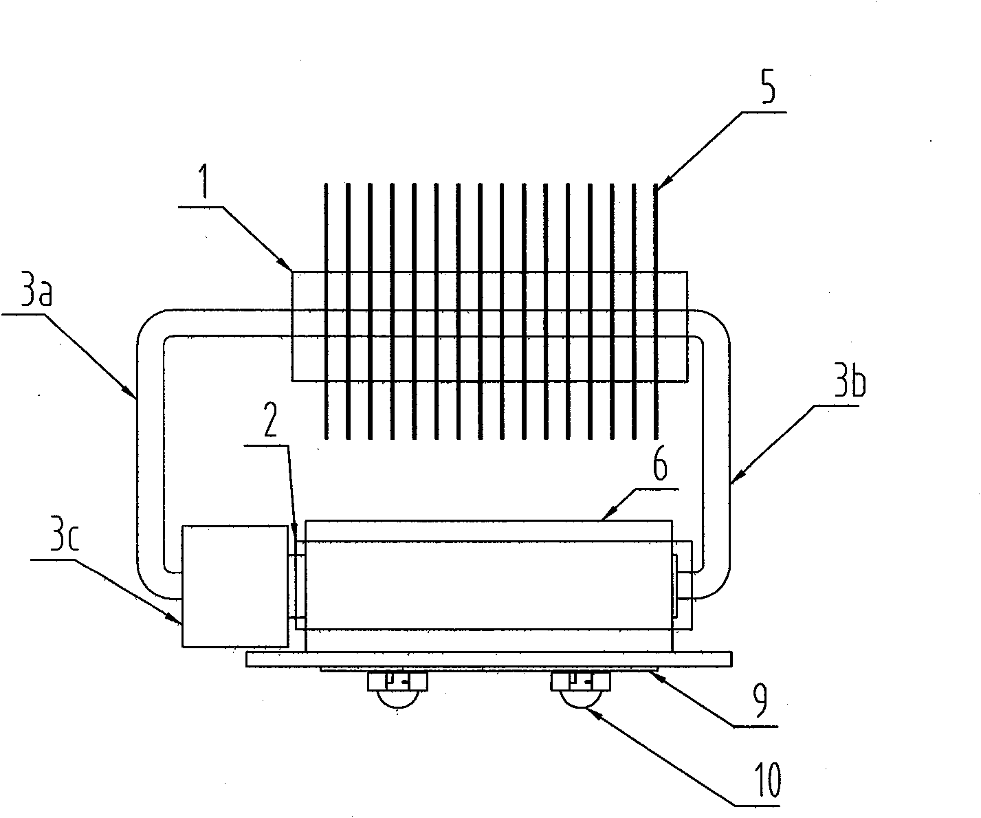
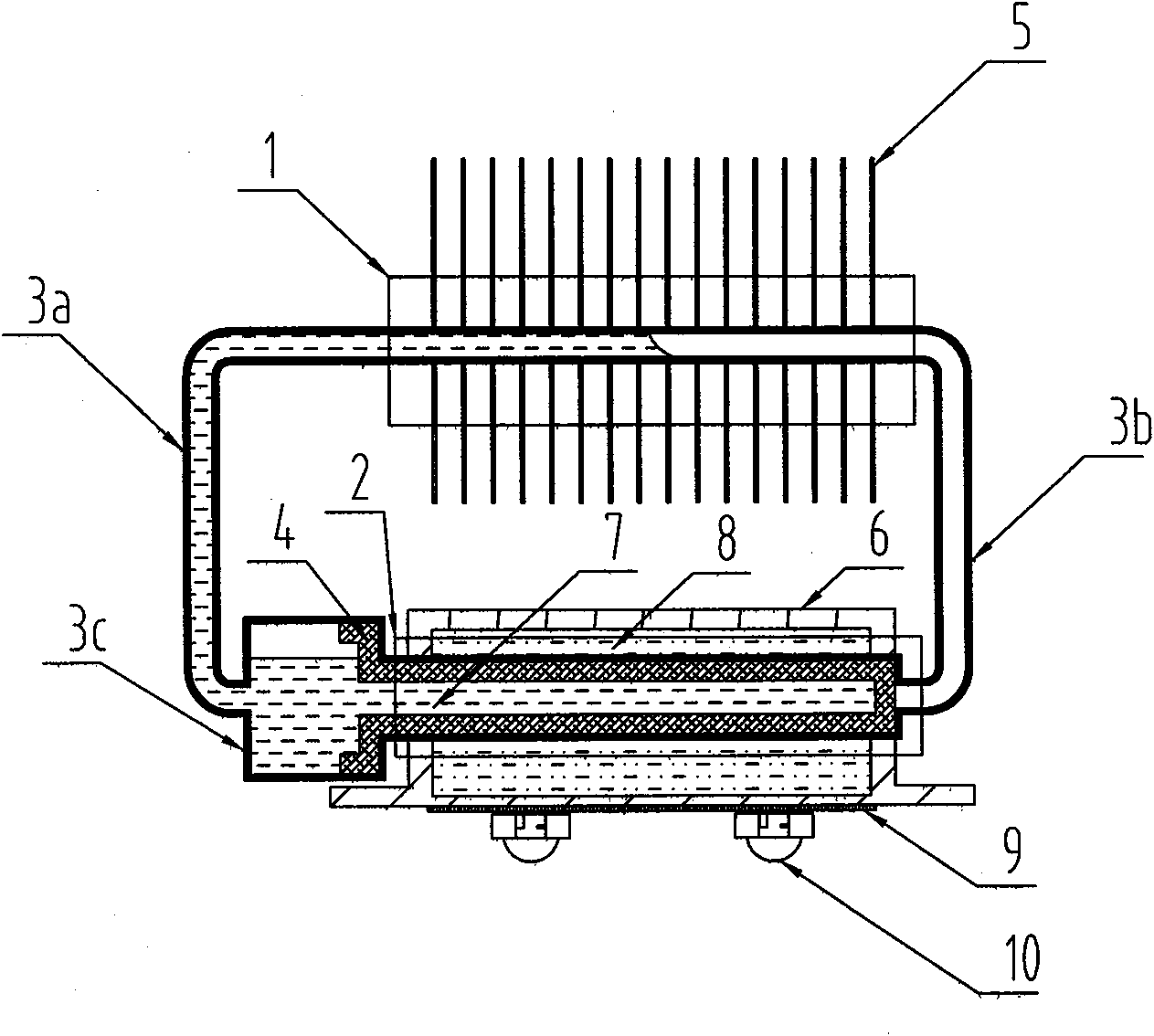
[0017] Such as figure 1 , figure 2 As shown, the high thermal conductivity soaking box loop heat pipe cooling device for heat dissipation of LED lamps is composed of heat pipes, heat sinks 5, high thermal conductivity soaking box 6, and high thermal conductivity liquid 8. The cross-sectional shape of the high thermal conductivity soaking box 6 is square, rectangular or circular, and the material of the high thermal conductivity soaking box is a metal material with high thermal conductivity, which is arranged on the back of the heat source surface (the LED circuit substrate 9 and the LED light source 10 of the LED lamp) . The heat pipe is a primary loop circulation pipe, which is divided into an evaporation section 2, a return section 3a, a steam section 3b, a compensation chamber 3c, and a condensation section 1. The evaporating section 2 passes through the high thermal conductivity soaking box 6 and is connected into one body by welding. A sealed cavity is formed between t...


PUM


Abstract

The invention discloses a heat radiation device of a heat pipe of a loop of a temperature-equalization tank with high heat conductivity, which can be applied to the field of the high-power illumination of LEDs or the field of the application of an electronic element. The device comprises a heat pipe, heat radiation fins, a temperature-equalization tank with high heat conductivity, liquid with high heat conductivity and the like, wherein an evaporation section of the heat pipe passes through the inside of the temperature-equalization tank with high heat conductivity and is connected with the temperature-equalization tank with high heat conductivity into a whole by a welding mode, a sealing cavity is formed between the temperature-equalization tank with high heat conductivity and the evaporation section, the liquid with high heat conductivity is filled into the sealing cavity, the heat radiation fins are arranged on a condensation section outside the temperature-equalization tank with high heat conductivity, an internal cavity of the heat pipe is pumped into proper vacuum, a capillary structure is arranged in the pipe, and an amount of working liquid is filled into the pipe. The invention has reasonable and compact structure, easy production and manufacture, high efficiency of heat conduction and high speed of heat radiation, is used for the heat radiation of an LED lamp, effectively lowers the temperature of an LED module, enhances the luminous efficiency of the LED, lowers the light enervation speed of the LED and prolongs the service life of the LED.

Description

technical field [0001] The invention relates to a heat transfer device, in particular to a heat pipe cooling device with a high thermal conductivity uniform temperature box which can be applied in the field of LED high-power lighting or the application field of electronic components requiring heat dissipation. Background technique [0002] High-power LEDs are being used more and more in lighting. At present, the heat dissipation problem of high-power LEDs is still a problem that hinders the rapid popularization of high-power LED lighting applications. Most of the electrical energy of high-power LEDs is converted into conduction heat. In addition, placing several or a large number of LEDs in a module to achieve the required brightness will cause difficulty in heat dissipation, and the temperature of the LED module will rise, resulting in LEDs. The lifespan is reduced, and the light decay of the LED is accelerated, and the efficiency and reliability of the LED driver and other...

Claims


Application Information

Patent Timeline
Patent Type & Authority Applications(China)
IPC IPC(8): F28D15/04F21V29/00F21Y101/02
Inventor 史杰
Owner 史杰
Why Eureka
Try Eureka