
Distiller condenser with solvent inflow structure in fur degreasing machine

A technology of condenser and degreasing machine, which is applied in steam/steam condenser, small raw hide/big raw hide/leather/fur treatment, small raw hide/large raw hide/leather skin/fur chemical treatment, etc., which can solve the personal injury of operators , gaseous solvent overflow, tetrachlorethylene solvent acidification or chemical composition decomposition, etc., to prevent personal injury and environmental pollution, reduce the return temperature of solvent, and reduce the grade of fur

Inactive Publication Date: 2010-02-03
上海雅森洗涤设备有限公司
View PDF0 Cites 4 Cited by
  • Summary
  • Abstract
  • Description
  • Claims
  • Application Information

AI Technical Summary

Problems solved by technology

[0007] 3. The gaseous solvent falls to the bottom of the cylinder and flows out directly after it hits the condensing coil to cool down and liquefies. There is no buffer zone, so the temperature of the recovered solvent is relatively high
[0008] 4. The gaseous solvent flows freely after entering the cylinder, and there is a temperature difference between the solvent condensed in contact with the condensing coil and the solvent condensed without contact with the condensing coil, and the temperature of all returning solvents cannot be guaranteed to be consistent
[0009] 5. When the supply of cooling water is insufficient or the flow rate of the gaseous solvent entering the cylinder is too large, the gaseous solvent may overflow from the outlet of the liquid solvent, and the uncondensed overflowing solvent gas is easily emitted outside the machine, causing pollution to the environment and personal injury to the operator
[0010] 6. Due to the high temperature of the recovered solvent, it is easy to cause the acidification of the tetrachlorethylene solvent or the decomposition of chemical components, causing damage, hardening or brittleness, and scale reduction to the degreased and washed fur.

Method used


Image

  • Distiller condenser with solvent inflow structure in fur degreasing machine
  • Distiller condenser with solvent inflow structure in fur degreasing machine
  • Distiller condenser with solvent inflow structure in fur degreasing machine

Examples


Embodiment Construction

[0018] Below in conjunction with accompanying drawing and specific embodiment the present invention is described in further detail:

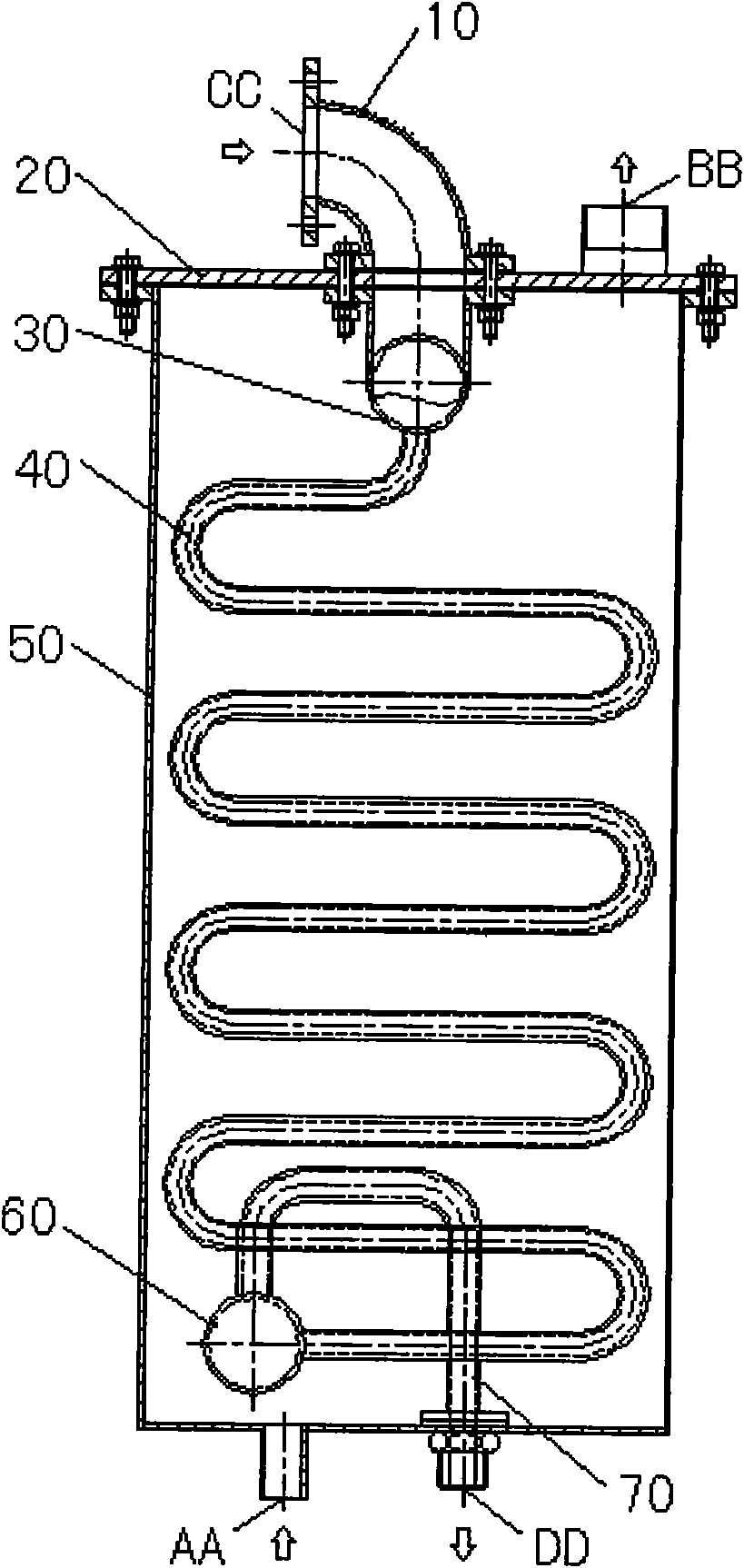
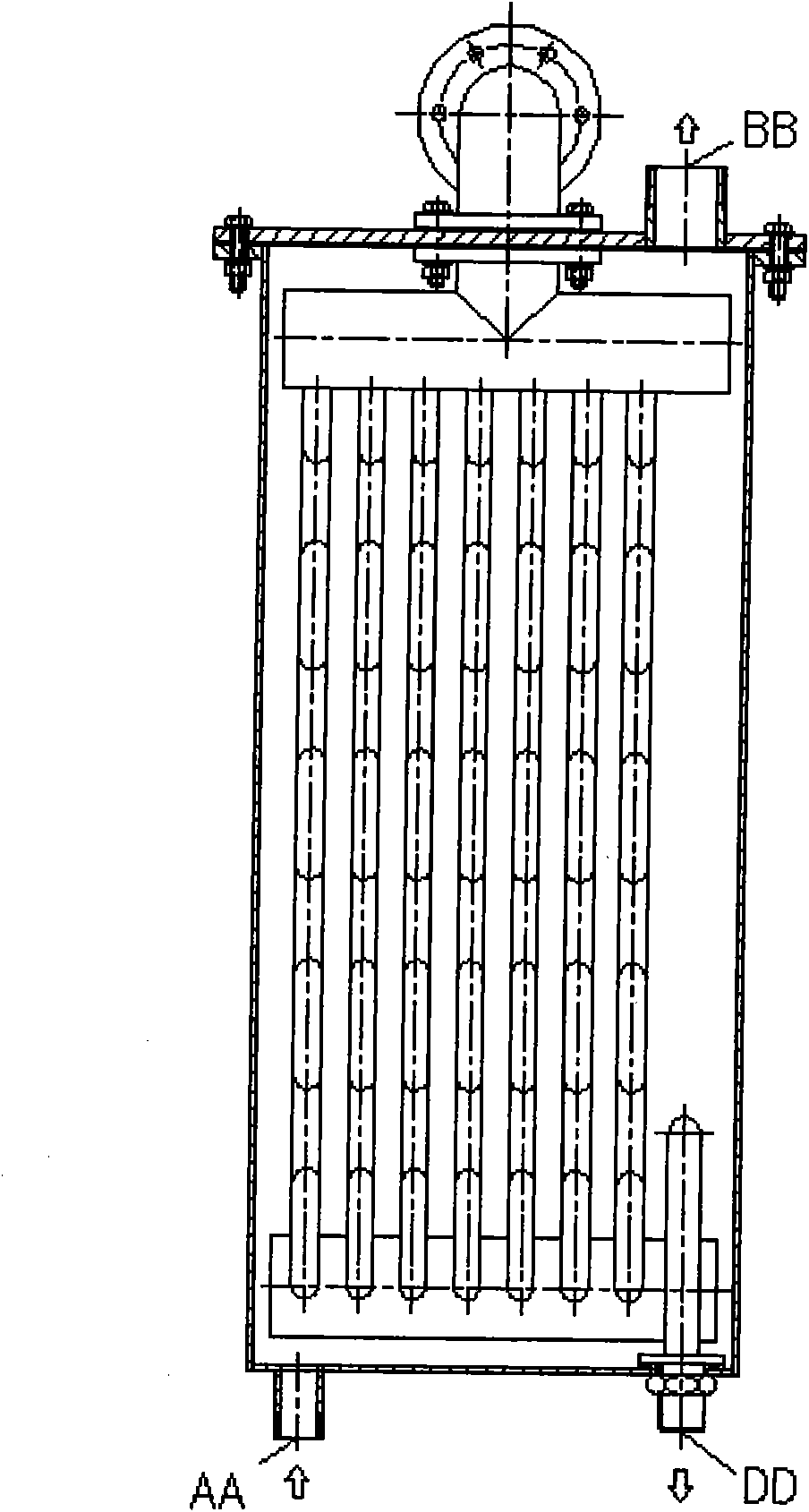
[0019] Depend on figure 2 , image 3 It can be seen that the present invention includes: a condenser cylinder 50; the condenser cylinder 50 is in sealing connection with the condenser cylinder cover 20 on the upper end surface; a cooling water inlet connection AA, a cooling water outlet connection BB, A gaseous solvent connection inlet CC and a liquid solvent outlet DD; the gaseous solvent connection inlet CC is arranged on the upper surface of the condenser cylinder cover 2 and connected to one end of the connecting elbow 10; the connecting elbow The other end of the head 10 is inside the condenser cylinder 50 and connected to one end of the upper confluence pipe 30; the other end of the upper confluence pipe 30 is connected to one end of the condensing coil 40; the other end of the condensing coil 40 passes through a The lower confluence pi...


PUM


Abstract

The invention relates to a distiller condenser with a solvent inflow structure in a fur degreasing machine. The structure of the distiller condenser is changed from the prior cylindrical structure toa square structure; the prior spiral cooling coil is changed into a condensing coil consisting of an upper bus tube, a lower bus tube, a plurality of rows of condensing bent pipes, a gaseous solvent inlet and a liquid returning bent pipe; in the prior structure, cooling water flows through the inside of the condensing coil, and the outside of the condensing coil is provided with a gaseous solventcondensing chamber; and the prior structure is changed into a structure in which gaseous solvent passes through the inside of the condensing coil to be condensed and the outside of the condensing coilis provided with a cooling water flowing chamber. The distiller condenser has the advantages that: the distiller condenser can reduce the consumption of the cooling water in operation, take full useof the cold energy of the cooling water, effectively reduce the liquid returning temperature of the solvent, and effectively prevent the overflow of the gaseous solvent from causing personal injuriesto operators and environmental pollution; and the condensed and recycled solvent does not damage degreased and cleaned furs and degrade fur grade due to acidification or component decomposition.

Description

technical field [0001] The invention relates to a dry cleaning machine or a fur degreasing machine, in particular to a distillation condenser in the fur degreasing machine. Background technique [0002] The fur degreasing machine is a kind of equipment suitable for degreasing and washing the oil on the fur of sheep, dog, rabbit, mink, fox, weasel, goose and other animals, or washing the semi-finished and finished garments made of the above fur. For dry cleaning equipment, the degreasing washing solvent is tetrachloroethylene (C 2 Cl 4 ). The difference between the fur degreasing machine and the general dry cleaning machine is that the rated loading capacity is relatively large, and the general rated loading capacity is about 30Kg to 150Kg; the tetrachlorethylene solvent contains a lot of animal fat and other stains after degreasing and washing, and is generally not suitable for direct secondary cleaning. Use, must be recycled after distillation regeneration. Therefore, i...

Claims


Application Information

Patent Timeline
IPC IPC(8): C14C15/00C14C1/08F28B1/02
Inventor 董小泉
Owner 上海雅森洗涤设备有限公司
Learn More