Photoelectric winding

A winding and photoelectric technology, applied in the field of inductance and electric equipment, can solve problems such as equipment and line damage

Inactive Publication Date: 2010-02-03
苑泽
View PDF0 Cites 6 Cited by
  • Summary
  • Abstract
  • Description
  • Claims
  • Application Information

AI Technical Summary

Problems solved by technology

In the process of use, once a fault occurs, the high temperature will cause damage

Method used


Image

  • Photoelectric winding
  • Photoelectric winding

Examples


Embodiment Construction

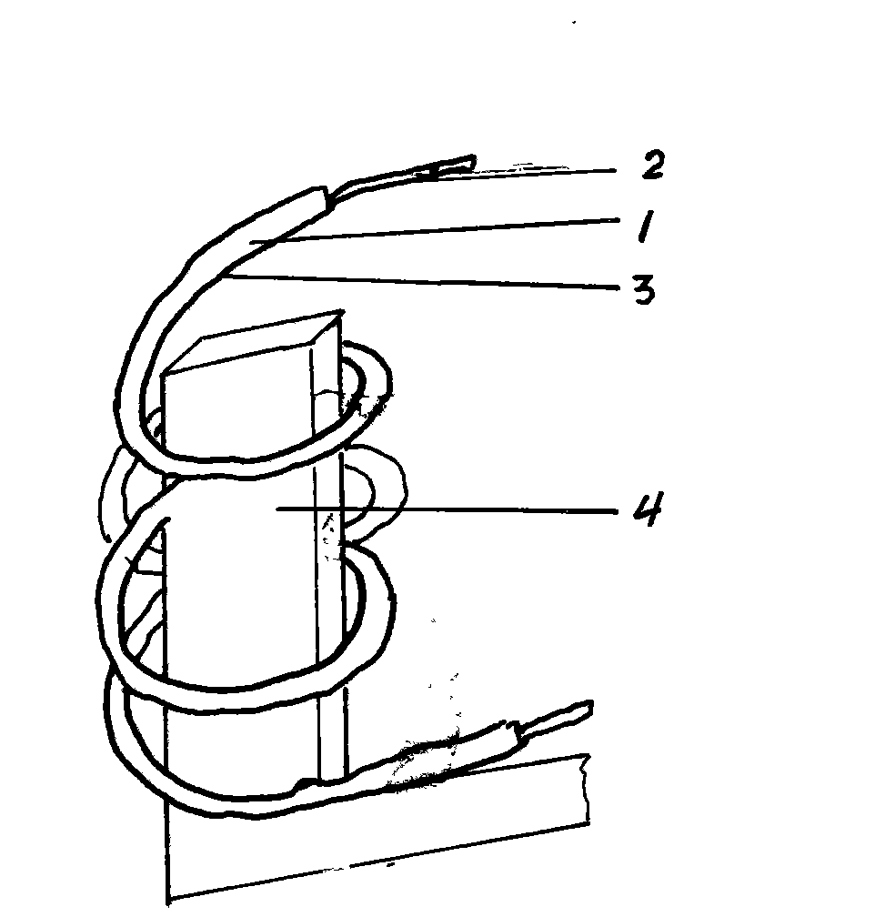
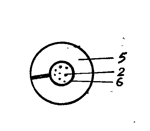
[0006] As shown in the figure, the photoelectric winding of the present invention is used for transformers, reactors, cores of inductors, generators, stators and rotors of motors working at a voltage of 0.1 kV to 1100 kV. The wires of the photoelectric windings are bare copper wires or bare aluminum wires 1, and the photoelectric windings can also sense or transmit relevant information such as temperature, current, or pressure while conducting electric energy. Light copper wire or light aluminum wire 1 is made by extruding optical fiber or fiber bundle 2 in fiber groove 6 of conductive metal copper or aluminum billet 5. Its mold cross section is circular, square or rectangular, and its surface may The insulating layer 3, the optical fiber or the optical fiber bundle 2 can be a single-mode optical fiber or a multi-mode optical fiber or a high-temperature optical fiber or a sensing optical fiber, and the surrounding of the optical fiber 2 can be filled with ointment. The bare co...


PUM


Abstract

The invention provides a photoelectric winding, which is used for a transformer from 0.1 kilovolt to 1100 kilovolt work voltage, a reactor, a cassette mechanism and an electric generator of the inductor, and a stator, a rotor, and the like, of an electric motor. The guide line of the photoelectric winding is photo copper wire or photo aluminum wire. The photoelectric winding transmits electrical energy, and can sense or transmit correlative information such as temperature or electric current or pressure, etc. The photo copper wire or the photo aluminum wire is manufactured by extruding opticalfiber or optical fiber bundle packed in electricity conducting metallic copper or aluminum billet. The photoelectric winding can sense and transmit correlative work condition information such as temperature, electric current, pressure, and the like, when the photoelectric winding works, therefore, the photoelectric winding leads power equipment to have a self-check alarming function, provides fundamental guarantee for the good operation of equipment and accident avoidance, is intellectualized electrical power telecommunication equipment, and has epoch-making meaning.

Description

technical field [0001] The invention relates to inductance and electric equipment widely used in electric power and telecommunication departments. Background technique [0002] The cores of various transformers, reactors and inductors in the electric power and telecommunications industries, as well as generators, stators and rotors of motors, all have windings made of wires. In the process of use, once a fault occurs, the high-temperature burnout will cause damage to the entire equipment and lines, and the consequences will be very serious. Whether it is possible to sense the working status of the above-mentioned equipment when it is running and transmit the relevant information to the monitoring equipment is a major concern of people. It is particularly important to develop inductive devices such as intelligent transformers with self-checking and alarming functions. Contents of the invention [0003] The present invention is designed to provide photoelectric windings wi...

Claims


Application Information

Patent Timeline
IPC IPC(8): H01F5/00H01F27/28H02K3/02H02K15/02G02B6/44
CPCH02K11/0047H02K11/001H01F5/00H02K3/02H02K11/0052H02K11/0057H02K11/20H02K11/25H02K11/26H02K11/27
Inventor 苑泽
Owner 苑泽
Why Eureka
Try Eureka