
Electron beam drawing apparatus and stage mechanism thereof

A technology of electron beam irradiation and gantry, which is applied in the direction of electron beam welding equipment, welding equipment, metal processing equipment, etc., and can solve the problem of reduced movement accuracy of X gantry

Inactive Publication Date: 2010-02-03
NUFLARE TECH INC
View PDF1 Cites 1 Cited by
  • Summary
  • Abstract
  • Description
  • Claims
  • Application Information

AI Technical Summary

Problems solved by technology

However, the elastic force of the bellows and the sliding friction resistance of the guide mechanism set to prevent buckling of the bellows reduce the movement accuracy of the X-gantry

Method used


Image

  • Electron beam drawing apparatus and stage mechanism thereof
  • Electron beam drawing apparatus and stage mechanism thereof
  • Electron beam drawing apparatus and stage mechanism thereof

Examples


Embodiment Construction

[0033] Embodiments of the present invention will be described below with reference to the accompanying drawings. In all the drawings cited below, the same reference numerals are used to designate substantially the same or equivalent components or parts.

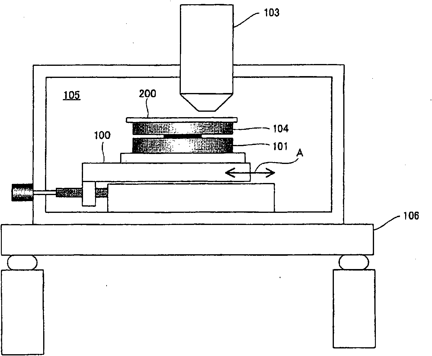
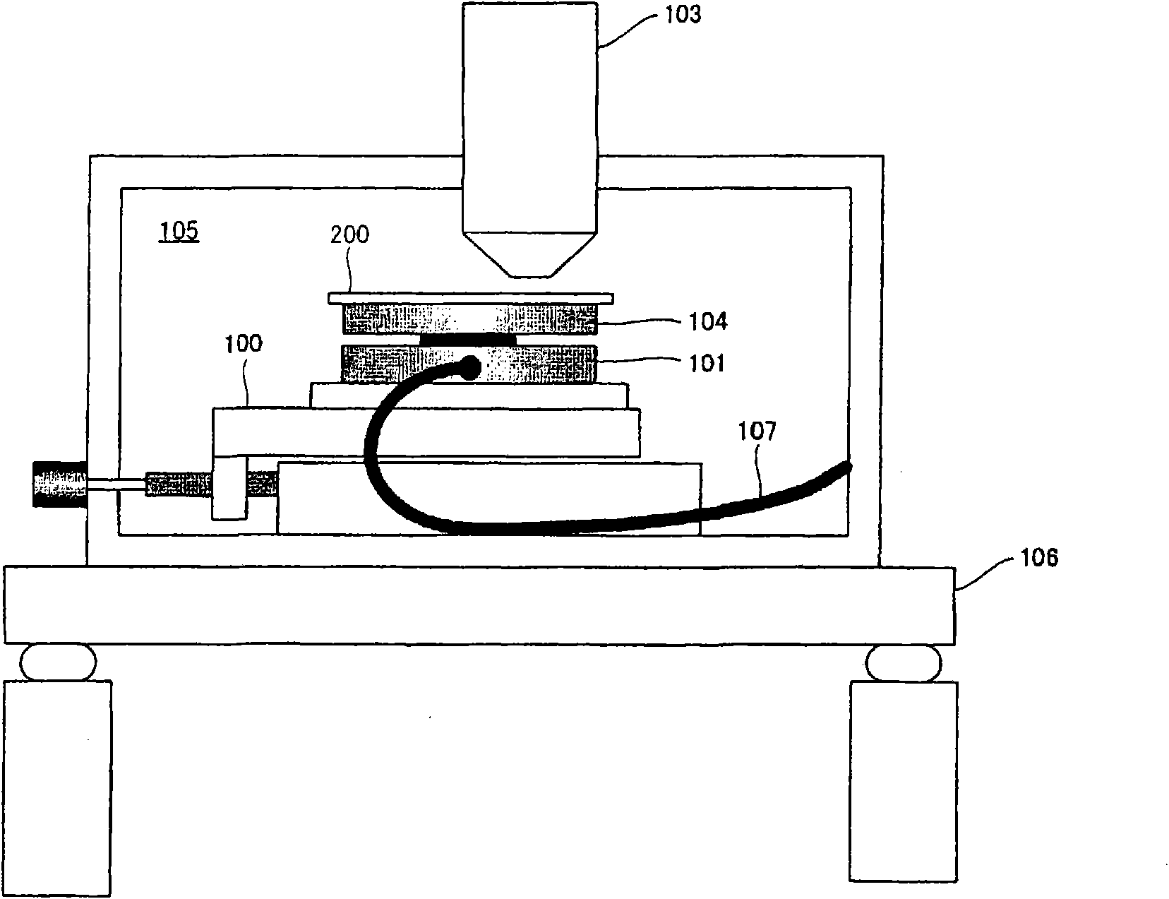
[0034] Figure 4 It is a cross-sectional view of a rotary table 1 using an aerostatic electric spindle as an embodiment of the present invention. The thrust plates 3, 4 and the swivel table 5 are connected to the rotary shaft 2 of the rotary gantry 1, so these parts form a rotary part. A journal bearing 6 and a thrust bearing 7 are placed facing the rotary shaft 2 and the thrust plates 3 , 4 with a slight gap, respectively. When the compressed air is supplied into the bearing inlet 8 , the compressed air is ejected via the supply passage 9 out of nozzle forming portions forming parts of the journal bearing 6 and the thrust bearing 7 . The rotary shaft 2 and the thrust plates 3 and 4 are supported by the compressed air in a...


PUM


Abstract

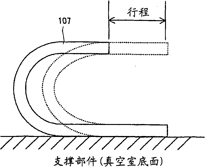
A positioning mechanism including a rotary stage and a linear motion stage is contained in a vacuum chamber and a pipe is connected to the positioning mechanism from the outside of the vacuum chamber.A space extending below the positioning mechanism is formed in the vacuum chamber. The pipes connecting the positioning mechanism and a vacuum partition wall to each other are so disposed in a generally U-shape that the pipes can be deformed in correspondence with the movement of the linear motion stage without contacting with the inner wall of the vacuum chamber in the space.

Description

technical field [0001] The present invention relates to an electron beam lithography equipment and its stand mechanism which can be used in the process of making master discs such as master recording discs. Background technique [0002] In the mastering process of master optical discs, pits and grooves are formed by exposing a resist film to a laser beam. The laser beam recorder (LBR) used in this master disc production process uses UV (ultraviolet), deep UV (extreme ultraviolet), etc. as its light source, and the beam diameter can be further reduced by deep UV. The exposure limit of a laser beam, that is, the recording density of an optical disc, is determined by the diffraction limit of light, which is determined by the wavelength of the light and the numerical aperture of the objective lens. In recent years, an electron beam lithography method used in semiconductor processing has been studied in order to form minute pits or grooves whose size exceeds the exposure limit o...

Claims


Application Information

Patent Timeline
Patent Type & Authority Applications(China)
IPC IPC(8): G11B7/26B23K15/00B23Q1/48
CPCG11B7/261
Inventor 北原弘昭
Owner NUFLARE TECH INC
Learn More