Processing method for waste water

A treatment method and technology for waste liquid, applied in water/sewage treatment, water/sewage treatment equipment, water/sludge/sewage treatment, etc., which can solve the problems of difficult reaction control, disordered decomposition reaction, and difficulty in oxidant treatment.

Inactive Publication Date: 2010-02-10
KK TOSHIBA
View PDF1 Cites 9 Cited by
  • Summary
  • Abstract
  • Description
  • Claims
  • Application Information

AI Technical Summary

Problems solved by technology

[0010] However, these methods have problems in that, as shown below, reaction control is difficult, or, by sub-addition of an oxidizing agent and a catalyst, new secondary wastes and by-products are generated
[0011] That is, 1) In the method of oxidation treatment using an oxidizing agent, there is a problem that not only the handling of the oxidizing agent is difficult, but also by-products are produced due to excessive reaction
2) In the oxidation method using a catalyst, there is a problem that not only the catalyst itself forms harmful secondary waste to cause harm, but also the reaction is difficult to control
3) In the method of utilizing reverse osmosis membrane pressure filtration, the existing problem is that the treatment cap

Method used


Image

  • Processing method for waste water
  • Processing method for waste water
  • Processing method for waste water

Examples


Embodiment 2

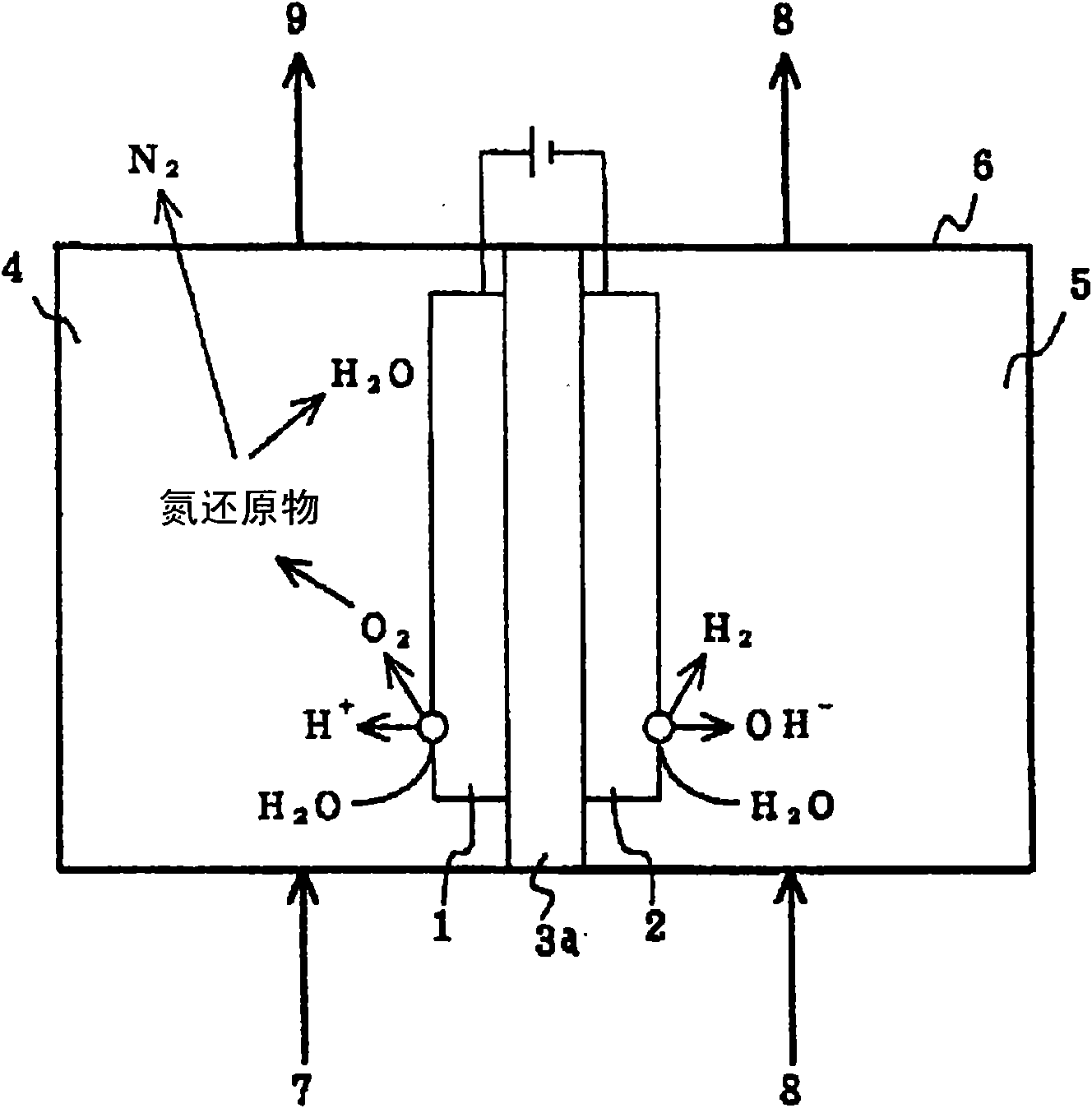
[0071] In Example 2, since the meshed anode 1 and cathode 2 are used, the contact interface area between the electrode and the electrolyte is significantly increased compared with the case of using a solid rod or plate electrode. Furthermore, since the anion exchange membrane 3a is arranged closely between the mesh-like anode 1 and cathode 2, the distance between the electrodes is shortened. Therefore, it is easy to cause an electrode reaction, so that the nitrogen reducing substances such as hydrazine and ammonium ions in the waste liquid 7 are efficiently oxidized in a short time.

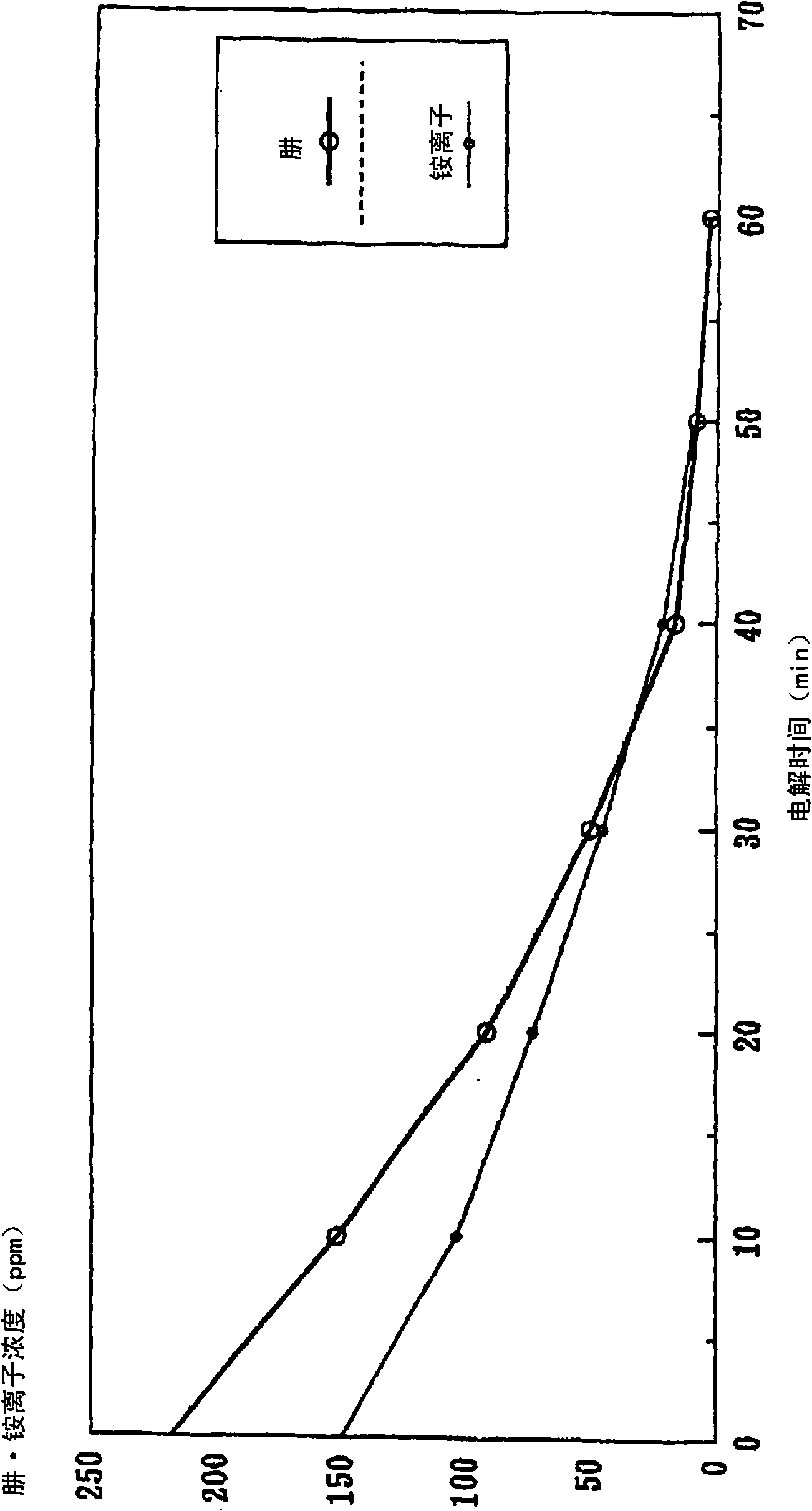
[0072] Figure 7 In the electrolytic cell 6 in which the anion exchange membrane 3a is arranged closely between the meshed anode 1 and the cathode 2, pure water is injected into the anode chamber 4 and the cathode chamber 5 for electrolysis, and the measured current changes with time. Graph. In addition, the electrolysis is in the electrolysis area of ​​0.75dm 2 , Applied voltage 10V (constant...

Embodiment 3

[0074] Example 3, such as Figure 8 As shown, a cation exchange membrane 3b is set between the anode 1 and the cathode 2, and the electrolytic cell 6, which is divided into the anode chamber 4 and the cathode chamber 5 by the cation exchange membrane 3b, will contain medium like nitrate ions and nitrite ions. Nitrogen oxide waste liquid 7 is injected into the cathode chamber 5, and pure water 8 is injected into the anode chamber 4 for electrolysis. Here, the anode 1 is composed of a material in which self-gold plating is performed on the surface of an iron base material, and has a mesh shape. The cathode 2 is made of SUS, and like the anode 1, has a mesh shape. A cation-exchange membrane (strongly acidic cation-exchange membrane) is loosely interposed between these electrodes, and the ion-exchange membrane is placed in close contact with each other.

[0075] The water in the waste liquid 7 injected into the cathode chamber 5 is reduced on the cathode 2 according to the follo...

Embodiment 4

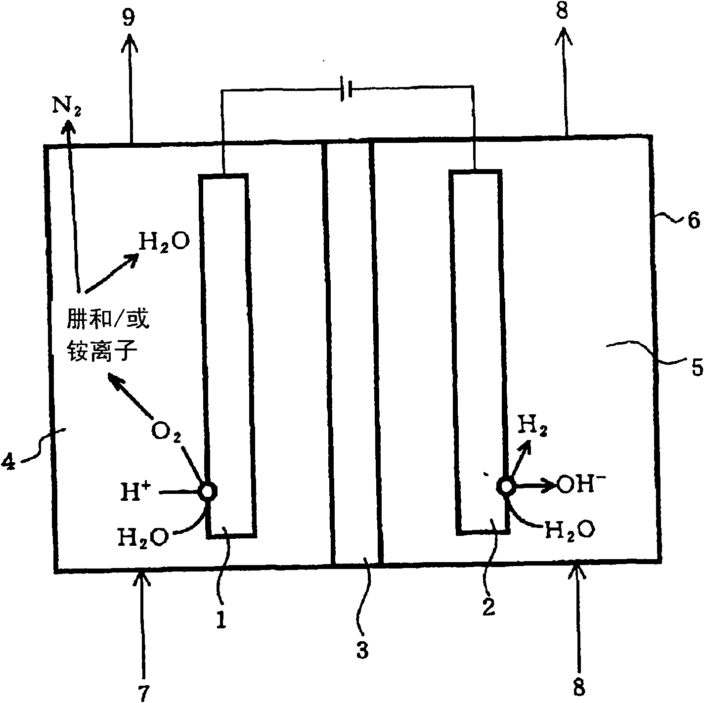
[0085] Example 4, such as Figure 11 As shown, a diaphragm 3 formed of aluminum oxide is arranged between any plate-shaped anode 1 and cathode 2, and is separated into an electrolytic cell 6 of an anode chamber 4 and a cathode chamber 5 by the diaphragm 3, and the anode chamber 4 Inject the waste liquid 7 containing any one of hydrazine and forged ions, at first inject pure water into the cathode chamber 5, and carry out the 1st electrolysis, the nitrogen reduction product (hydrazine and / or ammonium ion) in the waste liquid 7, by Oxygen generated on the anode 1 is oxidized to generate nitrogen gas. Next, inject the liquid 9 of this oxidation treatment into the cathode chamber 5, inject pure water into the anode chamber 4, or inject the waste liquid 7 again, and perform the second electrolysis to reduce the oxidizing substances in the waste liquid 7 deal with. Here, as the waste liquid 7 containing at least one of hydrazine and ions, for example, a waste liquid generated in a...


PUM


Abstract

The invention provides a processing method for waste water, including in the electrolytic bath, feeding pure water into the cathode room, feeding the waste water into the anode room for the electrolysis, and thereby oxidizing the reduced nitrogen compound in the waste water to nitrogen gas by oxygen generated from the water contained in the waste water; or feeding pure water into the anode room, feeding waste water into the cathode room for the electrolysis, and thereby reducing nitrogen oxide to nitrogen gas by the hydrogen generated from the water contained in the waste water; wherein a diaphragm made from alumina is provided between the anode and the cathode, at least one of the anode and the cathode is formed into a reticular structure or porous structure, moreover, the anode and the cathode are disposed in close proximity interposing the membrane therebetween. The processing method of waste water is capable of, under normal temperature and pressure, without generating the secondary waste, removing nitrogen compounds such as hydrazine, an ammonium ion, a nitrate ion, a nitrite ion, or the like as a nitrogen gas from the waste water.

Description

[0001] This application is a divisional application of Chinese Patent Application No.98123361.9 with the filing date of December 10, 1998 and the title of the invention being "Waste Liquid Treatment Method and Treatment Device". technical field [0002] The invention relates to a waste liquid treatment method and a treatment device thereof. In more detail, it is about the electrochemical oxidation or reduction reaction of nitrogen compounds, in the form of nitrogen, from nitrogen reducing substances (nitrogen hydrogen compounds) containing hydrazine and ammonium, nitrogen oxides such as nitrate ions and nitrite ions A method for removing nitrogen compounds such as nitrogen compounds from waste liquids. In addition, nitrogen compounds, nitrogen reducing substances, and nitrogen oxides in this specification include ionic states, respectively. Background technique [0003] Generally, in the deoxidation (oxidation prevention) and anticorrosion treatment of the water supply syst...

Claims


Application Information

Patent Timeline
IPC IPC(8): C02F1/469C25B1/00C02F1/461C02F1/467
CPCC02F1/467C02F2201/46115C02F2201/46185C02F2101/16C02F2001/46161C02F1/4672C02F2201/4611C02F1/4676
Inventor 藤畑健二关秀司寺田慎一
Owner KK TOSHIBA
Why Eureka
Try Eureka