

Decompressing fuel-oil floor washing device and method
A washing device and fuel technology, which is applied to ground devices, transportation and packaging, fuel tank safety measures, etc. good effect
- Summary
- Abstract
- Description
- Claims
- Application Information
AI Technical Summary
Problems solved by technology
Method used
Image

Examples
Embodiment 1
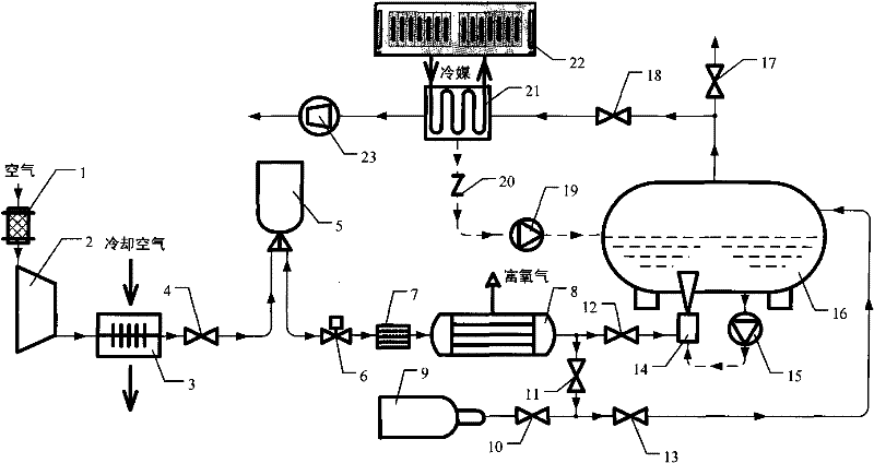
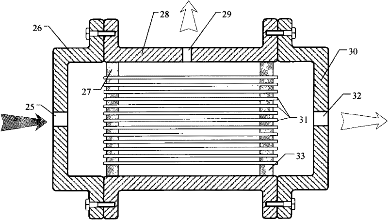
[0033] like figure 1 and image 3 As shown, the decompression type fuel oil floor washing device of the present invention includes an air pretreatment device, a nitrogen-enriched gas generator 8, a refueling truck oil tank 16 and a vacuum suction device 23, wherein:
[0034] The air pretreatment device includes an air filter 1, an air compressor 2, an aftercooler 3, an air exhaust shut-off valve 4, an air exhaust shut-off valve 4, an air storage bottle 5, and an air filter connected in series through an air delivery pipe in sequence. The flow regulating valve 6 and the filter 7, the air inlet of the air filter 1 communicates with the atmospheric environment, and the gas outlet of the filter 7 is connected with the air inlet 25 of the nitrogen-enriched gas generator 8 through a gas delivery pipe, by It can be seen that the device preprocesses the air in the atmospheric environment to obtain a quantitative amount of compressed air that has been purified, removed impurities and ...
Embodiment 2
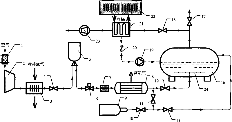
[0046] like figure 2 , Figure 4 and Figure 5 As shown, this embodiment is basically the same as Embodiment 1, but the difference between this embodiment and Embodiment 1 is that the gas outlet of the nitrogen-enriched gas flow regulating valve 12 is connected to the nitrogen-enriched gas distributor 24 through a gas delivery pipe, and the nitrogen-enriched gas distribution The device 24 is placed under the lowest fuel level in the oil tank 16 of the refueling vehicle, and the nitrogen-rich distributor 24 includes a bracket 37 and a main pipeline installed on the bracket 37, and the nitrogen-rich distributor 24 is connected to the fuel truck through the bracket 37. The inner wall of the oil tank 16 is fixed, the main pipeline is provided with a gas inlet pipe 38, and the body of the main pipeline is connected with more than one branch pipeline, and each branch pipeline is provided with a number of small gas outlet holes 36 .
[0047] Therefore, in the present embodiment, ...
PUM
 Abstract
Description
Claims
Application Information