
Decompressing fuel-oil floor washing device and method

A washing device and fuel oil technology, which is applied to ground installations, transportation and packaging, fuel tank safety measures, etc., can solve the problems of increased volume, weight, power consumption, and low efficiency of nitrogen-enriched gas generators, and achieve improved safety and improved oxygen dissolution. The effect of reducing and improving efficiency

Inactive Publication Date: 2013-04-24
NANJING UNIV OF AERONAUTICS & ASTRONAUTICS
View PDF0 Cites 2 Cited by
  • Summary
  • Abstract
  • Description
  • Claims
  • Application Information

AI Technical Summary

Problems solved by technology

[0009] However, the fuel oil ground washing system under normal pressure has the following problems: as the aircraft climbs higher, the amount of dissolved oxygen in the fuel decreases. Purity of nitrogen-rich gas, but the higher the purity of nitrogen-rich gas, the lower the efficiency of nitrogen-rich gas generator, which means that the volume weight work of each equipment in the scrubber, including compressor, filter, aftercooler and generator Increased consumption

Method used


Image

  • Decompressing fuel-oil floor washing device and method
  • Decompressing fuel-oil floor washing device and method
  • Decompressing fuel-oil floor washing device and method

Examples


Embodiment 1

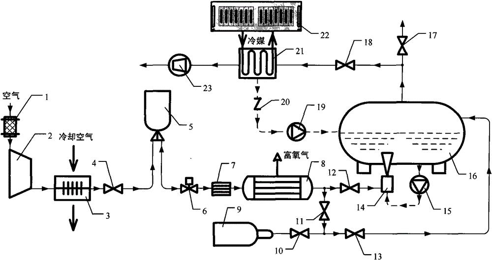
[0033] Such as figure 1 and image 3 As shown, the decompression type fuel oil floor washing device of the present invention includes an air pretreatment device, a nitrogen-enriched gas generator 8, a refueling truck oil tank 16 and a vacuum suction device 23, wherein:

[0034] The air pretreatment device includes an air filter 1, an air compressor 2, an aftercooler 3, an air exhaust shut-off valve 4, an air exhaust shut-off valve 4, an air storage bottle 5, and an air filter connected in series through an air delivery pipe in sequence. The flow regulating valve 6 and the filter 7, the air inlet of the air filter 1 communicates with the atmospheric environment, and the gas outlet of the filter 7 is connected with the air inlet 25 of the nitrogen-enriched gas generator 8 through a gas delivery pipe, by It can be seen that the device preprocesses the air in the atmospheric environment to obtain a quantitative amount of compressed air that has been purified, removed impurities a...

Embodiment 2

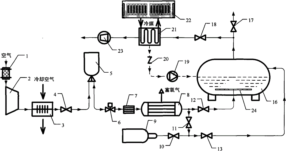
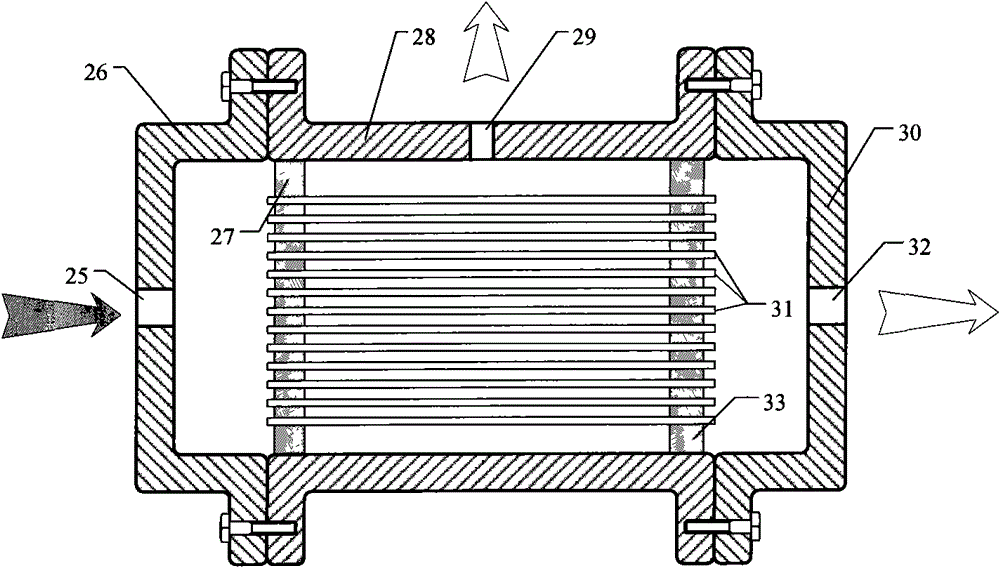
[0046] Such as figure 2 , Figure 4 and Figure 5 As shown, this embodiment is basically the same as Embodiment 1, but the difference between this embodiment and Embodiment 1 is that the gas outlet of the nitrogen-enriched gas flow regulating valve 12 is connected to the nitrogen-enriched gas distributor 24 through a gas delivery pipe, and the nitrogen-enriched gas distribution The device 24 is placed under the lowest fuel level in the oil tank 16 of the refueling vehicle, and the nitrogen-rich distributor 24 includes a bracket 37 and a main pipeline installed on the bracket 37, and the nitrogen-rich distributor 24 is connected to the fuel truck through the bracket 37. The inner wall of the oil tank 16 is fixed, the main pipeline is provided with a gas inlet pipe 38, and the body of the main pipeline is connected with more than one branch pipeline, and each branch pipeline is provided with a number of small gas outlet holes 36 .

[0047] Therefore, in the present embodimen...


PUM


Abstract

The invention discloses a decompressing fuel-oil floor washing device and a method, wherein, a vehicle nitrogen-manufacturing system is utilized to generate nitrogen-rich gas, firstly, the nitrogen-rich gas is adopted to wash the upper gas-phase space of the fuel-oil for an oil tank of a refueling truck, and then the oxygen content of the gas-phase space is decreased, and then, the nitrogen-rich gas is led into the fuel oil through a gas-oil mixer or a nitrogen-rich gas distributor which is arranged under fuel-oil liquid level, meanwhile, the pressure in the oil tank of the refueling truck isled to be lower than the environmental pressure through utilizing the suctioning of a vacuum suction device, thereby effectively increasing the treatment effect of fuel-oil washing inert; compared with the ordinary pressure washing, the oxygen content in the fuel-oil after decompressing washing is lower, therefore, the airplane can be ensured have no or have trace dissolved oxygen to escape when the airplane is at cruising altitude, thereby increasing the safety of the oil tank of the airplane. Additionally, after the washing is ended, the upper gas-phase space of the fuel-oil is filled with the nitrogen-rich gas of high purity, in order to ensure that the oxygen content can not increase caused by the mixing of external air in the fuel gas after the refueling truck is parked for a long period of time.

Description

technical field [0001] The invention belongs to the technical field of fire prevention and explosion protection, and relates to an aircraft fuel inertization treatment method and device, in particular to a decompression type fuel oil ground washing method and device. Background technique [0002] With the improvement of the flight speed and performance of aircraft, the increase of aerodynamic heating and heat load of electronic equipment brought about by it makes modern military aircraft generally tend to adopt fuel integrated thermal management technology. Simply put, fuel oil is used as a heat sink. For military aircraft, according to statistics, even if fuel oil is not used as a heat sink, fire or explosion of its fuel system has become one of the main causes of its crash. And when the comprehensive fuel thermal management technology is adopted, it will further increase the temperature of the aircraft fuel tank, that is to say, it will also increase the probability of th...

Claims


Application Information

Patent Timeline
Patent Type & Authority Patents(China)
IPC IPC(8): B64D37/32B64F1/36
Inventor 冯诗愚刘卫华高秀峰刘小芳鹿世化
Owner NANJING UNIV OF AERONAUTICS & ASTRONAUTICS
Learn More