Minisize thermoelectric generator

A thermoelectric power generation and miniature technology, applied in the direction of generators/motors, electrical components, etc., can solve the problems of effective heat load and energy density reduction, achieve the effects of reducing heat loss, improving combustion efficiency, and increasing thermoelectric conversion

Inactive Publication Date: 2010-02-10
GUANGZHOU INST OF ENERGY CONVERSION - CHINESE ACAD OF SCI
View PDF0 Cites 11 Cited by
  • Summary
  • Abstract
  • Description
  • Claims
  • Application Information

AI Technical Summary

Problems solved by technology

However, on the one hand, the overall temperature of the catalytic reaction should be maintained at 500-600°C, w

Method used


Image

  • Minisize thermoelectric generator

Examples


Embodiment Construction

[0016] The content of the present invention will be further described below in conjunction with the accompanying drawings and embodiments.

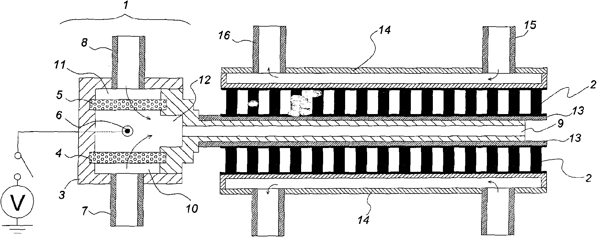
[0017] Such as figure 1 As shown, the micro thermoelectric power generation device is composed of a burner 1 and a thermoelectric module 2 . The burner 1 is composed of a housing 3 , a first perforated flat plate 4 , a second perforated flat plate 5 , and an electronic igniter 6 . A first fuel inlet 7 , a second fuel inlet 8 and an exhaust gas channel 9 are provided on the housing 3 .

[0018] In this embodiment, the size of the burner 1 is: 11mm×22mm×11mm (length×width×height), and the thickness of the casing 3 is: 1--1.5mm.

[0019] The first perforated plate 4 and the second perforated plate 5 are rectangular perforated plates with specifications: 7mm × 20mm × 1mm (length × width × height), they are parallel and aligned with each other, and the cavity in the housing 3 is separated It is a planar first air intake cavity 10, a second ...


PUM


Abstract

The invention provides a novel minisize thermoelectric generator with better combustion stability, combustion efficiency and thermoelectric efficiency than the prior minisize generating system. The minisize thermoelectric generator comprises a combustor and a thermoelectric module, wherein the combustor uses dimethyl ether as fuel; the inner cavity of the combustor is divided into a first gas inlet cavity, a second gas inlet cavity and a combustion chamber by a first multihole plate and a second multihole plate which are parallel and aligned; the combustion chamber is positioned between the first multihole plate and the second multihole plate; an exhaust channel just faces the center between the first multihole plate and the second multihole plate and is communicated with the combustion chamber; the exhaust channel and the heat end of the thermoelectric module are used for heat transmission; and the cold end of the thermoelectric module is provided with a water cooler. Compared with the prior thermoelectric generators, the minisize thermoelectric generator has the advantages of small size, high heat conversion efficiency and greatly enhanced performance, and is worthy of wide popularization.

Description

technical field [0001] The invention relates to a micro thermoelectric power generation device with a power requirement of several watts. Background technique [0002] Power supply power requirements range from a few watts to tens of watts. Power electromechanical products are widely used in military, medical, scientific research and daily life electronic products. At present, the energy supply system is mainly battery products, but battery products generally have low energy density and stable energy supply. Due to the shortcomings of short time and inconvenient battery life, new batteries such as micro fuel cell systems are also under research and development. The micro-power system based on fuel combustion has high energy density. For example, at a chemical energy-to-electricity conversion efficiency of 10%, the output power per unit mass or volume of the combustion-based micro-power system is much greater than that of the existing energy supply system, and the combustion-...

Claims


Application Information

Patent Timeline
IPC IPC(8): H02N11/00
Inventor 蒋利桥赵黛青汪小憨杨卫斌
Owner GUANGZHOU INST OF ENERGY CONVERSION - CHINESE ACAD OF SCI
Why Eureka
Try Eureka