
Nuclear magnetic resonance radio-frequency micro-coil and manufacturing method thereof

A technology of nuclear magnetic resonance and manufacturing method, which is applied in the direction of using nuclear magnetic resonance for analysis and magnetic resonance measurement. Uniformity of spin excitation, high manufacturing precision, and high uniformity of magnetic field distribution

Inactive Publication Date: 2010-02-17
INST OF ELECTRICAL ENG CHINESE ACAD OF SCI
View PDF2 Cites 14 Cited by
  • Summary
  • Abstract
  • Description
  • Claims
  • Application Information

AI Technical Summary

Problems solved by technology

[0007] The purpose of the present invention is to overcome the shortcomings that the conventional nuclear magnetic resonance detection probe cannot perform micro-sample detection, the magnetic field of the existing planar micro-coil is uneven, and the existing Helmholtz type micro-coil needs to be further miniaturized and the quality factor is not high. The invention provides a new type of Helmholtz microcoil and its manufacturing process

Method used


Image

  • Nuclear magnetic resonance radio-frequency micro-coil and manufacturing method thereof
  • Nuclear magnetic resonance radio-frequency micro-coil and manufacturing method thereof
  • Nuclear magnetic resonance radio-frequency micro-coil and manufacturing method thereof

Examples


Embodiment Construction

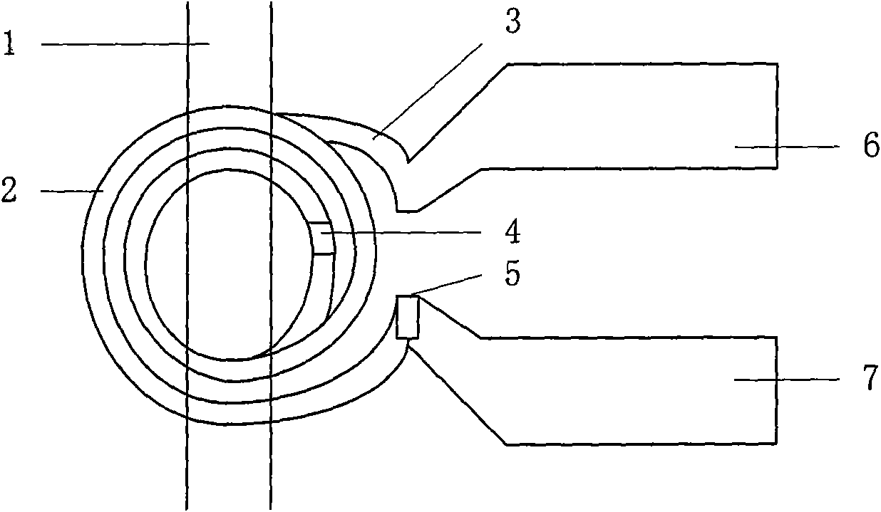
[0031] Such as figure 1 As shown, the Helmholtz-type nuclear magnetic resonance radio frequency microcoil of the present invention is composed of a top layer sub-coil 2, a bottom layer sub-coil 3, an inner via hole 4, an outer via hole 5, a first pad 6 and a second pad 7. The via hole 4 is located at the connection between the bottom layer sub-coil 3 and the top layer sub-coil 2, so as to realize the electrical connection between the bottom layer sub-coil 3 and the top layer sub-coil 2, and the outer via 5 is located between the top layer sub-coil 2 and the second pad 7 to realize the electrical connection between the top sub-coil 2 and the pad 7, that is, the first pad 6, the bottom sub-coil 3, the inner via 4, the top sub-coil 2, the outer via 5 and the second pad 7 in sequence electrical connection. The microchannel 1 containing the sample is located between the top sub-coil 2 and the bottom sub-coil 3 , and is parallel to both the top sub-coil 2 and the bottom sub-coil 3 ...


PUM


Abstract

The invention relates to a nuclear magnetic resonance radio-frequency micro-coil, comprising an upper flat subcoil and a lower flat subcoil which are mutually parallel, i.e. a top layer subcoil (2) and a bottom layer subcoil (3). The two flat subcoils have the same shape, and the distance between the subcoils is larger than or equal to the inside radius of the subcoils; the two flat subcoils are connected through a wire; a micro channel (1) used for containing a sample is positioned between and parallel with the top layer subcoil (2) and the bottom layer subcoil (3). An inner through hole (4)is positioned at the joint between the bottom layer subcoil (3) and the top layer subcoil (2); and an outer through hole (5) is positioned at the joint between the top layer subcoil (2) an a second bonding pad (7). The invention can emit radio-frequency pulse signal and (or) receive free induction decay echo signals coming from a tested object. The micro-coil is manufactured based on SU-8 photoresist by utilizing a micro-electro-mechanical system process on a Pyrex substrate (12). The invention can be used for nuclear magnetic resonance test of a nano-liter bio-chemical sample.

Description

technical field [0001] The invention relates to a nuclear magnetic resonance radio frequency coil, in particular to a radio frequency microcoil with uniform Helmholtz magnetic field and a manufacturing method thereof. Background technique [0002] At present, conventional nuclear magnetic resonance radio frequency coils are made of copper wires, which are used to transmit pulse trains from radio frequency power amplifiers to excite the measured samples, and / or receive Echo signal generated during the process. By amplifying, demodulating, detecting and Fourier transforming the obtained weak echo signals, the spectral lines about the nuclides contained in the sample to be tested can be obtained. information about the composition and composition of the molecule. [0003] Based on different application fields and the shape of the sample to be tested, NMR radio frequency coils are solenoid-shaped, planar spiral, and saddle-shaped. At present, the widely used 5mm probe is based ...

Claims


Application Information

Patent Timeline
IPC IPC(8): G01R33/34G01N24/08
Inventor 李晓南王明宋涛
Owner INST OF ELECTRICAL ENG CHINESE ACAD OF SCI
Learn More