Stacked coil device and manufacturing method thereof

A technology of laminated coils and manufacturing methods, applied in coil manufacturing, transformer/inductor coils/windings/connections, inductors with magnetic cores, etc., which can solve the problem of magnetic property degradation of magnetic ceramics, internal conductor disconnection, internal conductors Thickness and other problems, to achieve the effect of relieving internal stress, sufficient stress, and good characteristics

Inactive Publication Date: 2010-02-17
MURATA MFG CO LTD
View PDF1 Cites 9 Cited by
  • Summary
  • Abstract
  • Description
  • Claims
  • Application Information

AI Technical Summary

Problems solved by technology

[0003] In addition, the laminated coil device obtained by firing the magnetic ceramics and the inner conductor at the same time has the following problem: the internal stress caused by the difference in the thermal expansion coefficient between the magnetic ceramic layer and the inner conductor will deteriorate the magnetic properties of the magnetic ceramics. drop, causing a drop or deviation in the impedance value of the laminated coil device
[0006] Therefore, there is a problem that it is difficult to obtain a product with low DC resistance
In particular, if it is a small product such as a product with a size of 1.0 mm × 0.5 mm × 0.5 mm or a product with a size of 0.6 mm × 0.3 mm × 0.3 mm, there is the following problem: since it is necessary to make the magnetic ceramic layer thinner, it is difficult Since the internal conductor and the void are provided between the ceramic layers and the internal conductor is formed thick, not only the DC resistance cannot be reduced, but also the disconnection of the internal conductor due to impact or the like is likely to occur, and sufficient reliability cannot be ensured.

Method used


Image

  • Stacked coil device and manufacturing method thereof
  • Stacked coil device and manufacturing method thereof
  • Stacked coil device and manufacturing method thereof

Examples


Embodiment 1

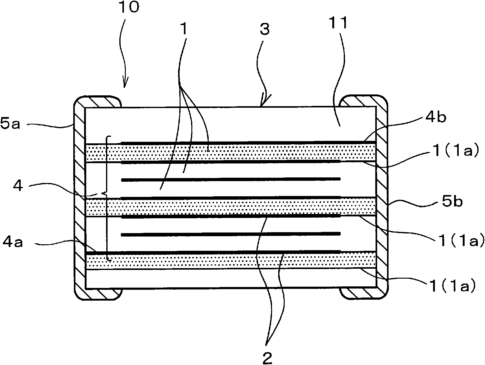
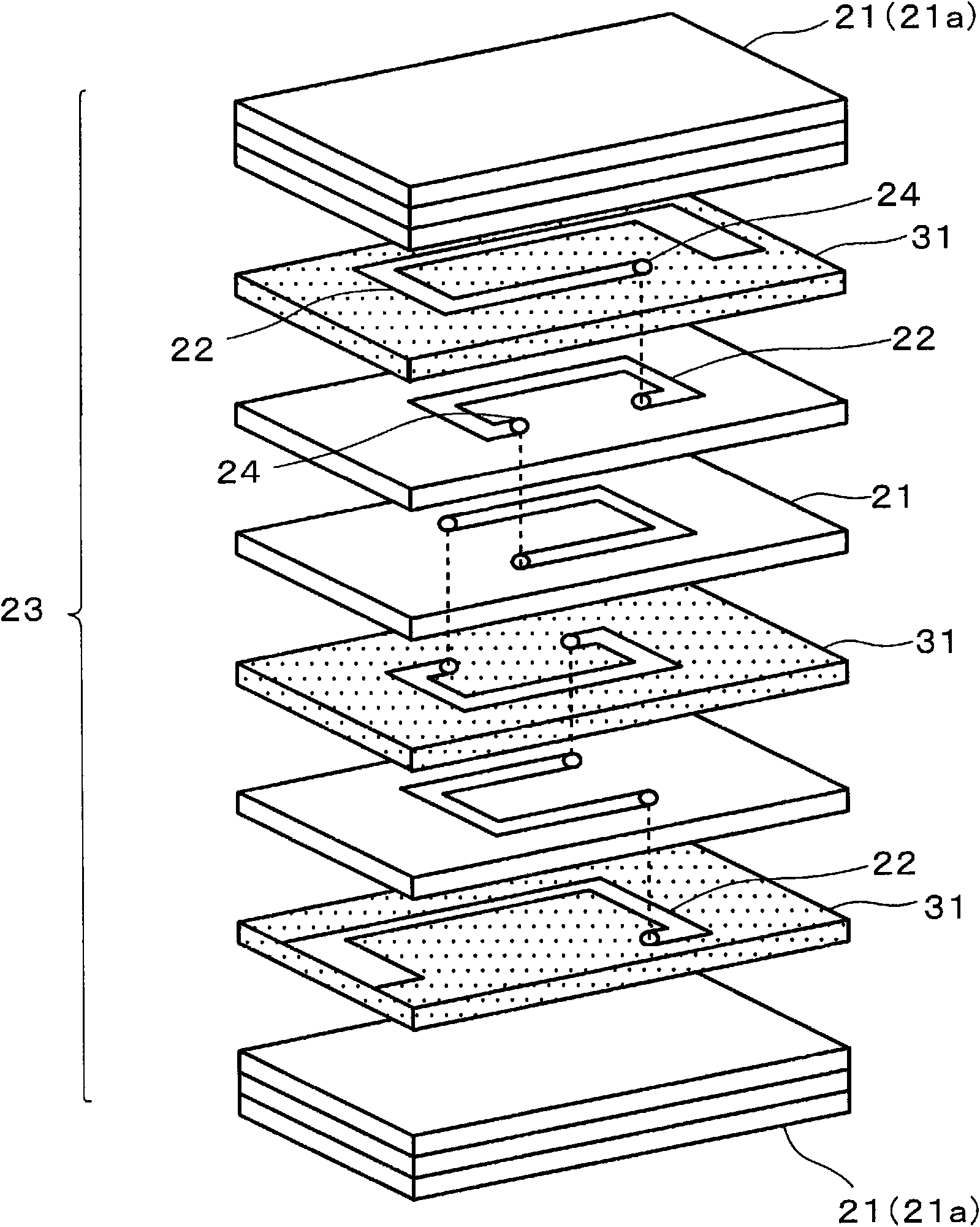
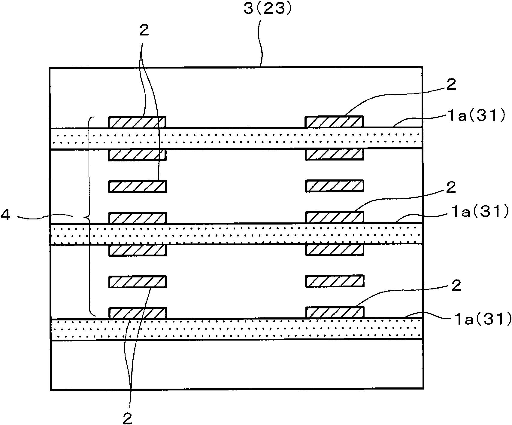
[0061] figure 1 is a schematic front sectional view showing the structure of a laminated coil device (a laminated impedance element in the first embodiment) according to an embodiment of the present invention, figure 2 yes means figure 1 An exploded perspective view of the fabrication method of the laminated coil device, image 3 yes figure 1 Side cross-sectional view of a laminated coil device.

[0062] This laminated coil device 10 includes a magnetic ceramic element 3, and the magnetic ceramic element 3 includes a laminated magnetic ceramic layer 1 and a spiral formed by connecting internal conductors 2 mainly composed of Ag laminated through the magnetic ceramic layer 1. shaped coil 4. Furthermore, a pair of external electrodes 5 a and 5 b are arranged at both ends of the magnetic ceramic element 3 so as to conduct conduction with both ends 4 a and 4 b of the helical coil 4 .

[0063] In addition, among the magnetic ceramic layers 1 constituting the magnetic ceramic ...


PUM

PropertyMeasurementUnit
thicknessaaaaaaaaaa

Abstract

The present invention provides a high characteristic and high reliability stacked coil device which alleviates the internal stress problem and does not form gap between the magnetic body ceramic layerand the internal conductor. The structure includes a magnetic body ceramic layer (1a). The magnetic body ceramic layer (1a) has a region with the pore space area rate of 6 to 20% from the flank of the magnetic body ceramic component (3) to the internal conductor. The structure has multiple layers of the magnetic body ceramic layer having a region with the pore space area rate of 6 to 20%. In thestructure, the gap does not exist on the interface of the internal conductor and the interface of the magnetic body ceramic surrounding the internal conductor, and the interface of the internal conductor is separated from the interface of the magnetic body ceramic. The flank of the magnetic body ceramic component is soaked through a region of the magnetic body ceramic layer with the pore space area rate of 6 to 20%, so that the acidic solution arrives in the interfaces of the internal conductor and the magnetic body ceramic surrounding the internal conductor, to cut off the combination of theinterface of the internal conductor and the interface of the interface of the magnetic body ceramic surrounding the internal conductor.

Description

technical field [0001] The present invention relates to a laminated coil device having a magnetic ceramic layer formed by firing a ceramic laminate formed by laminating a magnetic ceramic layer and a coil-forming internal conductor mainly composed of Ag. The interior of the element is equipped with a helical coil structure. Background technique [0002] In recent years, the demand for miniaturization of electronic devices has been increasing, and the mainstream of coil devices has gradually shifted to multilayer coil devices. [0003] In addition, the laminated coil device obtained by firing the magnetic ceramics and the inner conductor at the same time has the following problem: the internal stress caused by the difference in the thermal expansion coefficient between the magnetic ceramic layer and the inner conductor will deteriorate the magnetic properties of the magnetic ceramics. The drop causes a drop or deviation in the impedance value of the laminated coil device. ...

Claims


Application Information

Patent Timeline
Patent Type & Authority Applications(China)
IPC IPC(8): H01F17/04H01F27/28H01F41/04
Inventor 河野大司河野上正晴黑部淳司
Owner MURATA MFG CO LTD
Why Eureka
Try Eureka