

Method for welding composited tube at bonding interface of carbon steel/stainless steel machinery
A technology of interface compounding and welding method, which is applied in the direction of welding medium, welding equipment, welding equipment, etc., can solve the problems of increasing the difficulty of welding of composite pipes, difficult alignment of base layer and lining layer, low pass rate of flaw detection, etc. Excellent mechanical properties and corrosion resistance, avoid oxidation, and facilitate construction
- Summary
- Abstract
- Description
- Claims
- Application Information
AI Technical Summary
Problems solved by technology
Method used
Image

Examples
Embodiment 1
[0061] In this embodiment, the welded carbon steel / stainless steel mechanical bonding interface composite pipe 10 is a composite pipe composed of a stainless steel lining pipe 1 made of 316L stainless steel and a carbon steel base pipe 2 made of 20G carbon steel, and Its specification is Φ76×(7+2)mm.
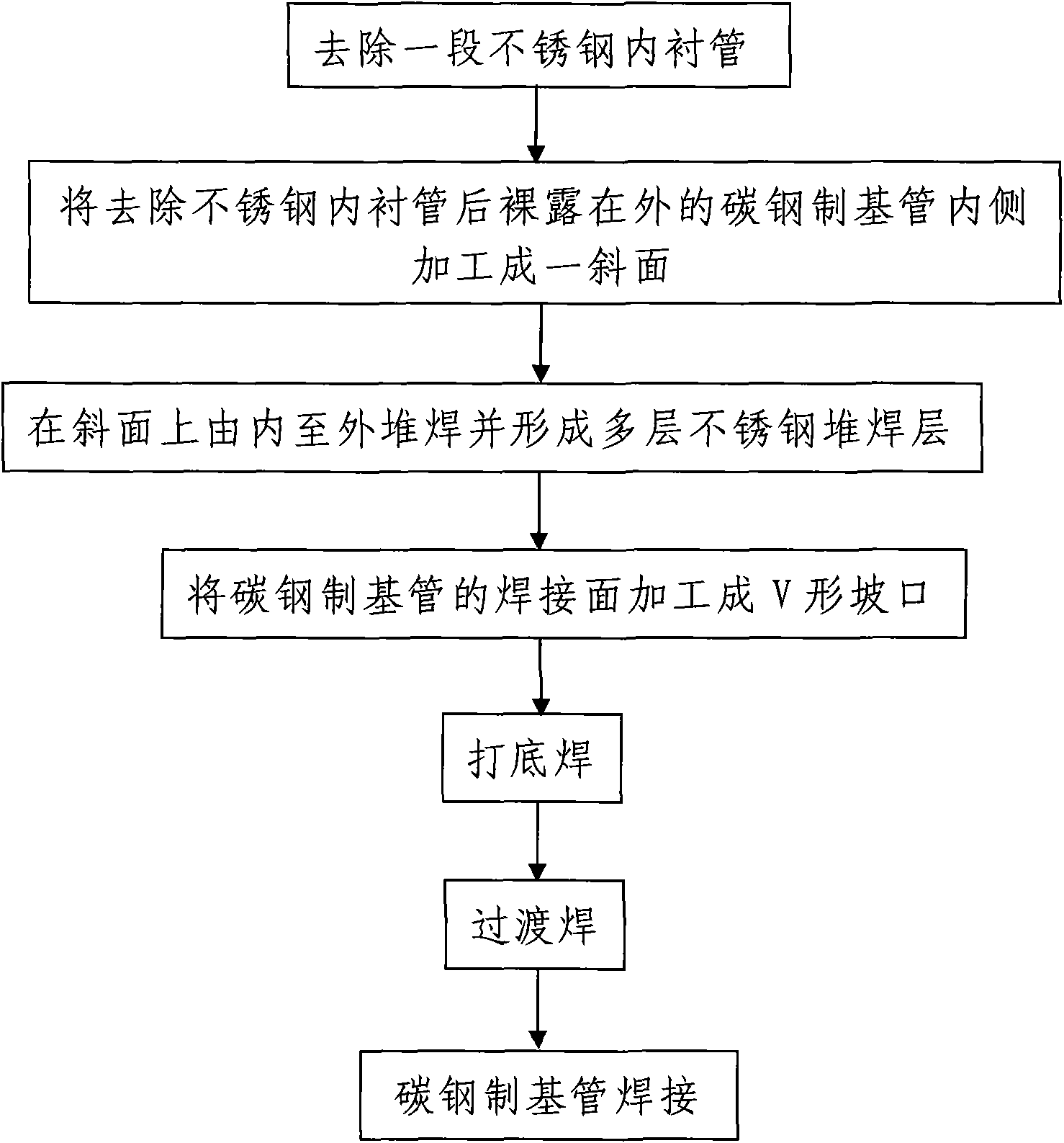
[0062] Step 1. Welding groove treatment, the treatment process is as follows:
[0063] 101. Using conventional mechanical processing methods, remove a section of 10mm long stainless steel lining pipe 1 from the outside to the inside at the end of the carbon steel / stainless steel mechanical bonding interface composite pipe 10 to be welded.
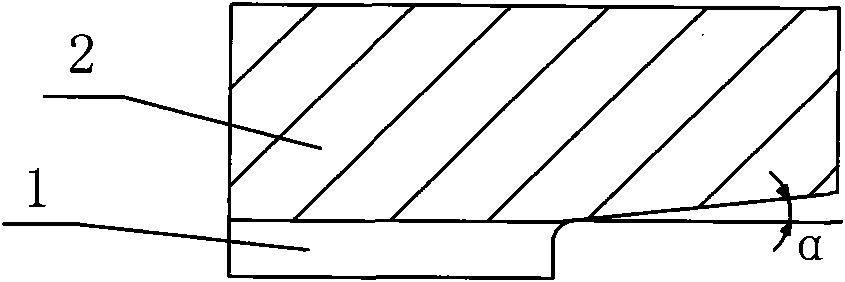
[0064] 102. Process the inner side of the exposed carbon steel base pipe 2 after removing the stainless steel lining pipe 1 to form an inwardly inclined slope from the outside to the inside, and the slope angle α of the slope is 5°. For details, see figure 2 .
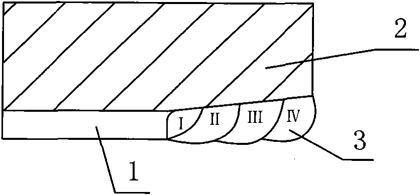
[0065] 103. Under the protection of argon gas, a TIG manual DC tungsten argon ...
Embodiment 2
[0080] In this embodiment, the welded carbon steel / stainless steel mechanical bonding interface composite pipe 10 is a composite pipe composed of a stainless steel lining pipe 1 made of 316L stainless steel and a carbon steel base pipe 2 made of 20G carbon steel, and Its specification is Φ56×(5+1.5)mm. The difference from Example 1 is: in step 101, a conventional mechanical processing method is adopted, and at the end of the carbon steel / stainless steel mechanically bonded interface composite pipe 10 to be welded, a section of stainless steel lining pipe 1 with a length of 8 mm is removed from the outside to the inside; In step 102, the inclination angle α of the inclined surface processed from outside to inside is 3°; in step 103, the welding current during surfacing welding is 90A, and the flow rate of shielding gas used in the welding process is 13L / min. After the surfacing welding is completed, a total of 3 layers of stainless steel surfacing welding layers 3 are formed on...
Embodiment 3
[0086] In this embodiment, the welded carbon steel / stainless steel mechanical bonding interface composite pipe 10 is a composite pipe composed of a stainless steel lining pipe 1 made of 316L stainless steel and a carbon steel base pipe 2 made of 20G carbon steel, and Its specification is Φ96×(9+3)mm. The difference from Example 1 is that in step 101, a conventional mechanical processing method is adopted, and at the end of the carbon steel / stainless steel mechanically bonded interface composite pipe 10 to be welded, a section of stainless steel lining pipe 1 with a length of 13 mm is removed from the outside to the inside; step In step 102, the inclination angle α of the inclined surface processed from the outside to the inside is 8°; the welding current during the surfacing welding in step 103 is 90A, and the flow rate of the shielding gas used in the welding process is 17L / min. After the surfacing welding is completed, a total of 5 layers of stainless steel surfacing welding...
PUM
 Abstract
Description
Claims
Application Information