
Temperature compensating circuit of radio frequency power amplifier

A technology of amplifier temperature and radio frequency power, which is applied to high frequency amplifiers, improved amplifiers to reduce temperature/power supply voltage changes, amplifiers, etc., can solve the problems of ineffective radio frequency power amplifiers, etc., to improve linearity indicators and improve compensation performance , The effect of gaining stable performance

Inactive Publication Date: 2010-02-24
ZYW MICROELECTRONICS
View PDF0 Cites 31 Cited by
  • Summary
  • Abstract
  • Description
  • Claims
  • Application Information

AI Technical Summary

Problems solved by technology

Therefore, current temperature compensation methods are not effective in reducing the gain variation of RF power amplifiers with temperature.

Method used


Image

  • Temperature compensating circuit of radio frequency power amplifier
  • Temperature compensating circuit of radio frequency power amplifier
  • Temperature compensating circuit of radio frequency power amplifier

Examples


Embodiment Construction

[0017] In order to facilitate the understanding of those skilled in the art, the present invention will be further described in detail below in conjunction with the accompanying drawings and embodiments.

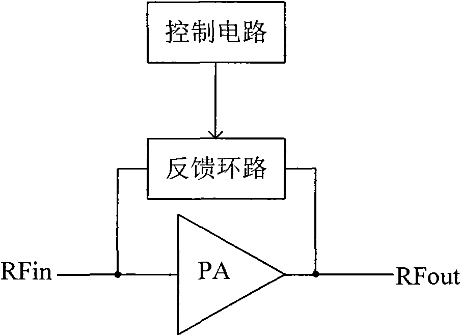
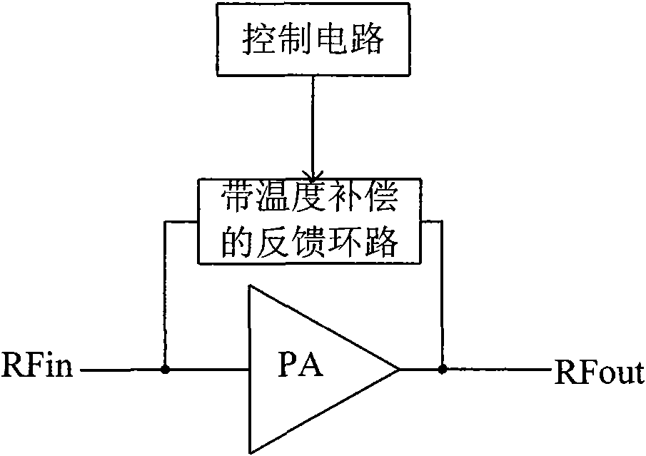
[0018] figure 1 It is a functional block diagram of Embodiment 1 of the temperature compensation circuit. As shown in the figure, the control circuit is connected to the feedback loop, and the feedback loop is connected between the input and the output of the radio frequency power amplifier. The implementation of this embodiment is to use the control circuit to generate a control voltage V that follows the chip temperature change tf , and its functional relation is V tf =V tf0 +f(T), where f(T) is a temperature compensation function, and then use this control voltage to control the feedback amount of the RF power amplifier feedback loop, the amplification factor β=qI of the GaAs HBT device c / KT can be known, in the assumed bias current I c Under the condition of not ch...


PUM


Abstract

The invention discloses a temperature compensating circuit of a radio frequency power amplifier with stable gain function. The temperature compensating circuit comprises a control circuit, wherein thecontrol circuit generates control voltage V<tf> which can be changed along with the change of the chip temperature of the radio frequency power amplifier so as to regulate the feedback quantity of afeedback loop of the radio frequency power amplifier, the feedback loop is connected between the input end and the output end of the radio frequency power amplifier or the control circuit generates control voltage V<bias> which can be changed along with the change of the temperature of the radio frequency power amplifier to regulate the bias current of a bias circuit of the radio frequency power amplifier, and the bias circuit is connected with the input end of the radio frequency power amplifier. On the premise that the indexes of efficiency, and the like of the radio frequency power amplifier are not influenced, the temperature compensating circuit can reduce the grain change along with temperature change, change the feedback quantity of the feedback loop, improve the linearity index ofthe amplifier simultaneously and achieve simple structure and low cost.

Description

technical field [0001] The invention relates to the technical field of radio frequency power amplifiers, in particular to a temperature compensation circuit for radio frequency power amplifiers with a stable gain function. Background technique [0002] RF power amplifier is a key component in various wireless communication system transmitters. Each communication standard has strict requirements on its indicators. With the increase of data transmission volume, the current 3G standard puts forward more requirements for RF power amplifier. Strict requirements. On the basis of high linearity and high efficiency, the RF power amplifier is also required to have good temperature characteristics in the entire temperature range. [0003] Gallium arsenide heterojunction device (GaAs HBT) is a radio frequency device with high linearity and high efficiency performance, which is widely used in the design of linear power amplifiers in mobile communication systems. There is a large deviat...

Claims


Application Information

Patent Timeline
Patent Type & Authority Applications(China)
IPC IPC(8): H03F1/30H03F3/189
CPCH03F2200/144H03F2200/141H03F3/19H03F2200/18H03F1/34H03F2200/447
Inventor 彭凤雄
Owner ZYW MICROELECTRONICS
Learn More