
Initial stage rain water flow discharging device

A technology for initial rainwater and rainwater collection. It is applied in water supply installations, drinking water installations, and general water supply conservation. It can solve problems such as affecting the quality of clean rainwater, difficulty, and reverse diffusion of pollutants.

Inactive Publication Date: 2010-03-03
CHONGQING UNIV
View PDF8 Cites 24 Cited by
  • Summary
  • Abstract
  • Description
  • Claims
  • Application Information

AI Technical Summary

Problems solved by technology

When the floating ball is partially submerged, there will be a space of a certain height between the water surface of the discarded rainwater and the blocked position of the water hole, so that the device needs a larger vertical height to store the same amount of rainwater under the same situation, which not only causes The waste of excavation in civil works, and the lower position also affects the rainwater of the discarded flow, which is emptied to the municipal sewage pipe by gravity
When the floating ball is completely submerged, since the floating ball is in direct contact with the inflow rainwater, the floating ball is easy to move with it due to the impact of the unevenness of the water flow intensity, making the water hole open and close continuously, causing pollution in the abandoned rainwater Reverse diffusion of pollutants, affecting the quality of clean rainwater in the later stage
For the patent application number 200610200799.4, the initial rainwater collection chamber has a built-in submersible pump, and the rain gauge stop device is equipped with an electronic liquid level gauge, which will be limited in the case of power shortage
For the patent with application number 200810244452.9, each functional unit is relatively independent and scattered, the space utilization rate is not high, the device occupies a large area, or the vertical height of the device is larger under the same conditions, and the cost of civil excavation increases; at the same time, the buried depth is larger. It is more difficult to empty the abandoned rainwater to the municipal sewage pipe by gravity, and it will also be very limited in the case of power shortage when using a pump to empty it

Method used


Image

  • Initial stage rain water flow discharging device
  • Initial stage rain water flow discharging device
  • Initial stage rain water flow discharging device

Examples


Embodiment Construction

[0021] The structure, working process, principle and effect of the present invention will be further described in detail below in conjunction with specific implementation methods, drawings and the present invention.

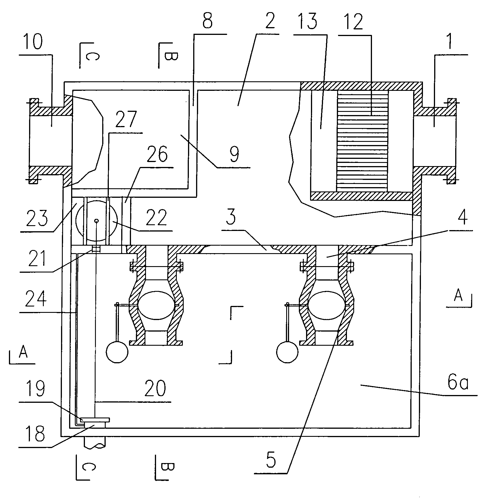
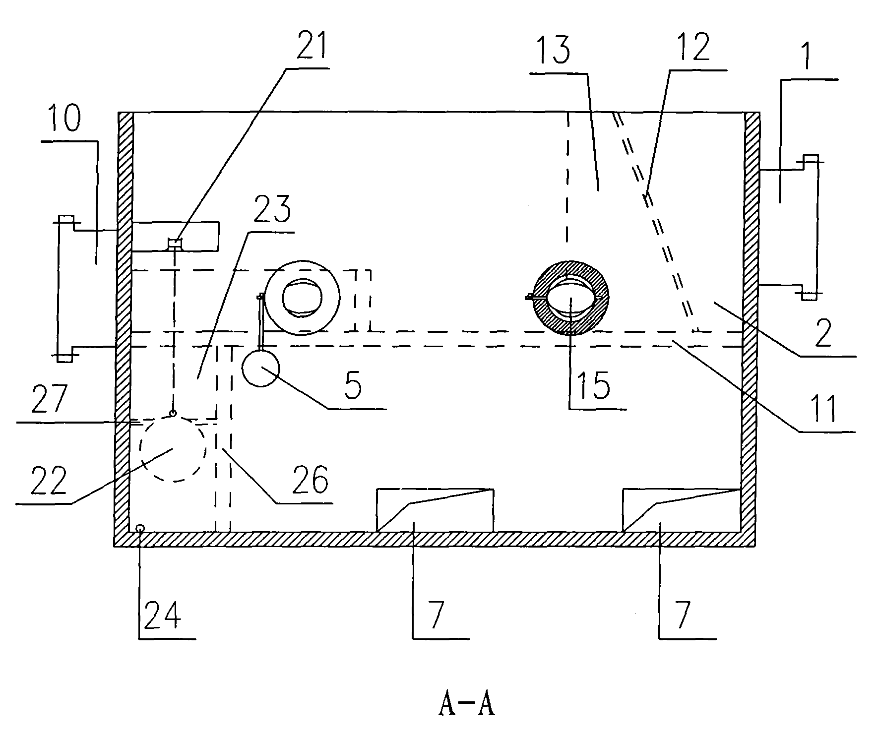
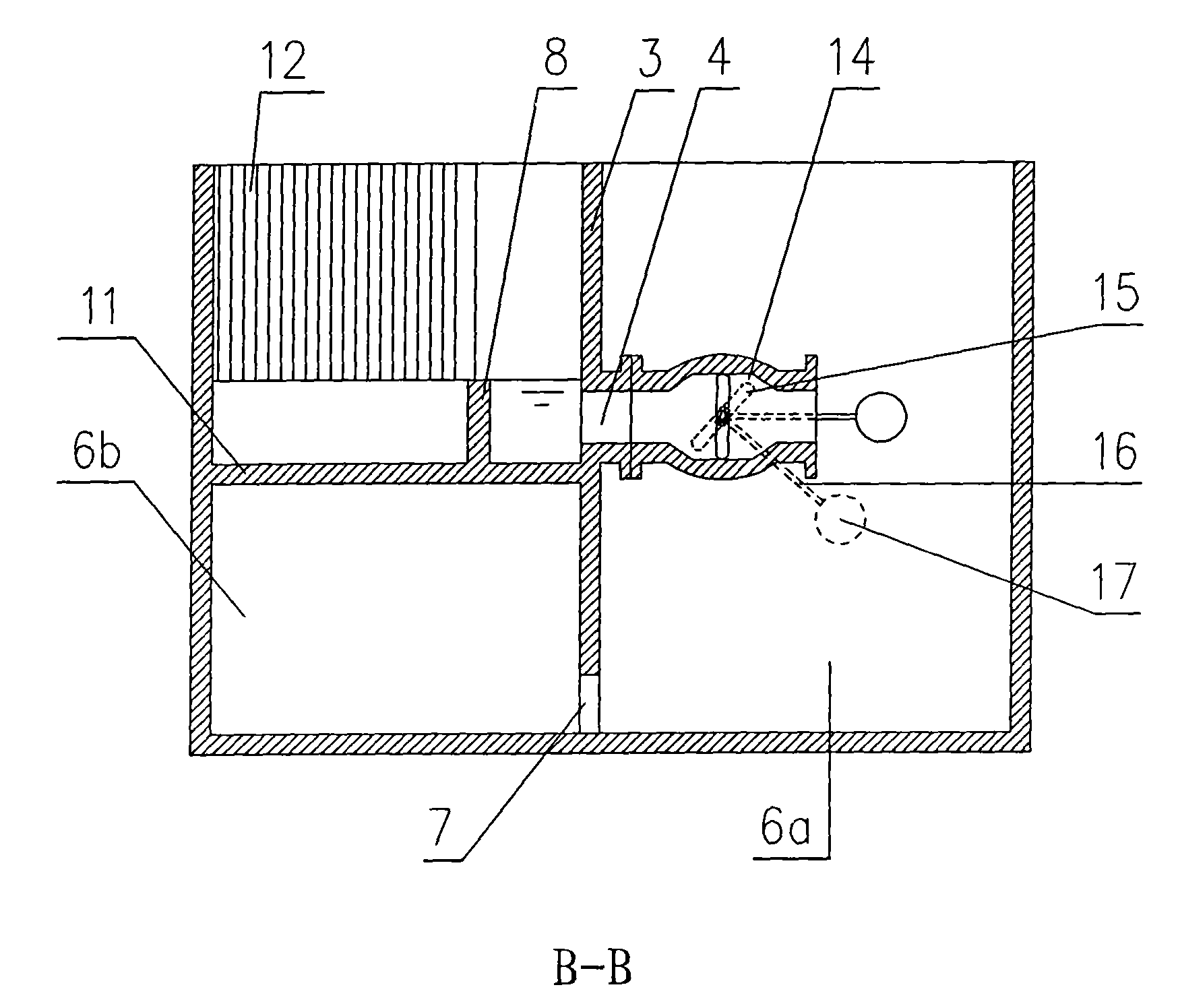
[0022] In specific implementation, such as Figure 1 to Figure 4 Shown: an initial rainwater abandonment device, including a container body connected to the rainwater collection pipe, the top of the container body is provided with an openable cover plate, and the interior of the container body is vertically provided with a waste flow partition 3, The discarding flow partition 3 divides the inside of the container into two spaces, one of which is the discarding flow front chamber 6a, and the middle part of the other space is provided with a multifunctional partition 11 horizontally, and below the multifunctional partition 11 is the discarding flow The rear chamber 6b, above the multi-functional partition 11, is a juxtaposed water collection chamber 2 and a diversi...


PUM


Abstract

The invention discloses an initial stage rain water flow discharging device which is mainly composed of an impoundment chamber, a flow discharging partition, a flow discharging water communicating pipe, a water flow control mechanism, a flow discharging front chamber, a flow discharging rear chamber, a shunting downflow weir, a shunting flow conduction chamber, a delayed automatic draining mechanism and the like. Compared with the prior art, the device of the invention can effectively separate severely polluted initial stage rain water from later stage clean rain water, has the advantages of optimized structure, compact structure, high space utilization ration, space occupation saving, no energy consumption, no need of staff operation, high automation degree, convenient management and thelike.

Description

technical field [0001] The invention relates to a device for collecting and utilizing rainwater resources, in particular to an initial rainwater discarding device used in a rainwater collection system. Background technique [0002] Due to the increasing shortage of fresh water resources, the collection and utilization of rainwater resources have been paid more and more attention. In some cities and regions where fresh water resources are scarce, various systems are constantly being used to collect and utilize rainwater. However, due to the high concentration of pollutants in the initial runoff rainwater, when it is collected together with the later clean rainwater, its storage and treatment to meet the water quality requirements are very uneconomical. Therefore, appropriate methods are used to discard the initial rainwater and become rainwater resources. An important aspect of utilization. [0003] The terminal rainwater pipes of the municipal rainwater pipe system are usu...

Claims


Application Information

Patent Timeline
IPC IPC(8): E03B3/02E03F5/00
CPCY02A20/108
Inventor 汪昆平郭劲松蒋绍阶
Owner CHONGQING UNIV
Learn More