Current amplification quick charge circuit used for hand-hold electronic device

An electronic device and fast charging technology, applied in the direction of circuit devices, battery circuit devices, current collectors, etc., can solve the problems of increased space occupied by printed circuit boards, manual debugging, waste of resources, etc., to improve charging speed and meet charging requirements , The effect of preventing mischarging

Active Publication Date: 2010-03-03
SUNWODA ELECTRONICS
View PDF8 Cites 10 Cited by
  • Summary
  • Abstract
  • Description
  • Claims
  • Application Information

AI Technical Summary

Problems solved by technology

[0005] 1. Use a dedicated charging management module, resulting in waste of resources; at the same time, the main chip of the handheld electronic device cannot monitor the charging state through the charging management module;
[0006] 2. Configuring a dedicated charging management chip and adding a current expansion circuit increases the cost of the handheld electronic device; and configuring a complicated current expansion circuit increases the space occupied by the printed circuit board, which is not in line with the development of miniaturized and portable handheld electronic devices Moreover, these added dedicated charging management chips and current expansion circuits need manual debugging, which increases production costs; and the charging current is not programmable, and it is not possible to implement small current pre-charging, constant-current charging, and constant-voltage charging stages for rechargeable batteries. Three-stage charging, affecting the life of the rechargeable battery

Method used


Image

  • Current amplification quick charge circuit used for hand-hold electronic device
  • Current amplification quick charge circuit used for hand-hold electronic device
  • Current amplification quick charge circuit used for hand-hold electronic device

Examples


Embodiment Construction

[0026] Further details will be given below in conjunction with the preferred embodiments shown in the accompanying drawings.

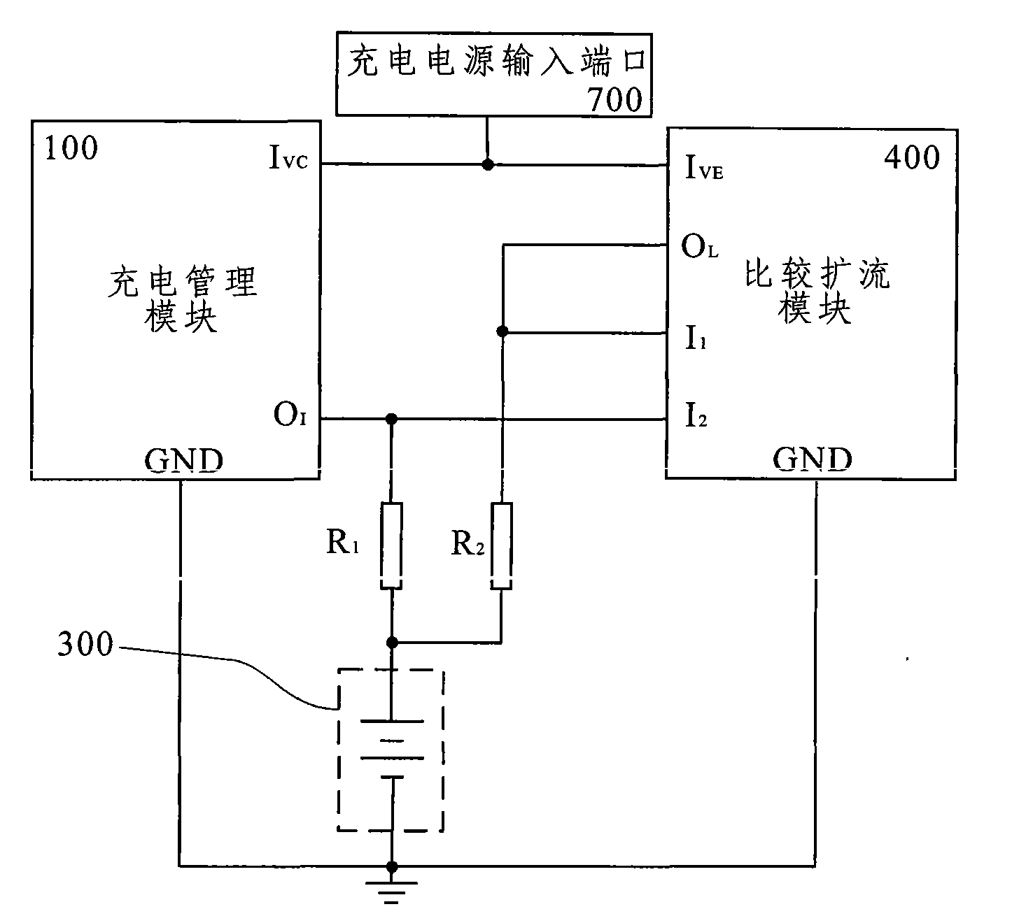
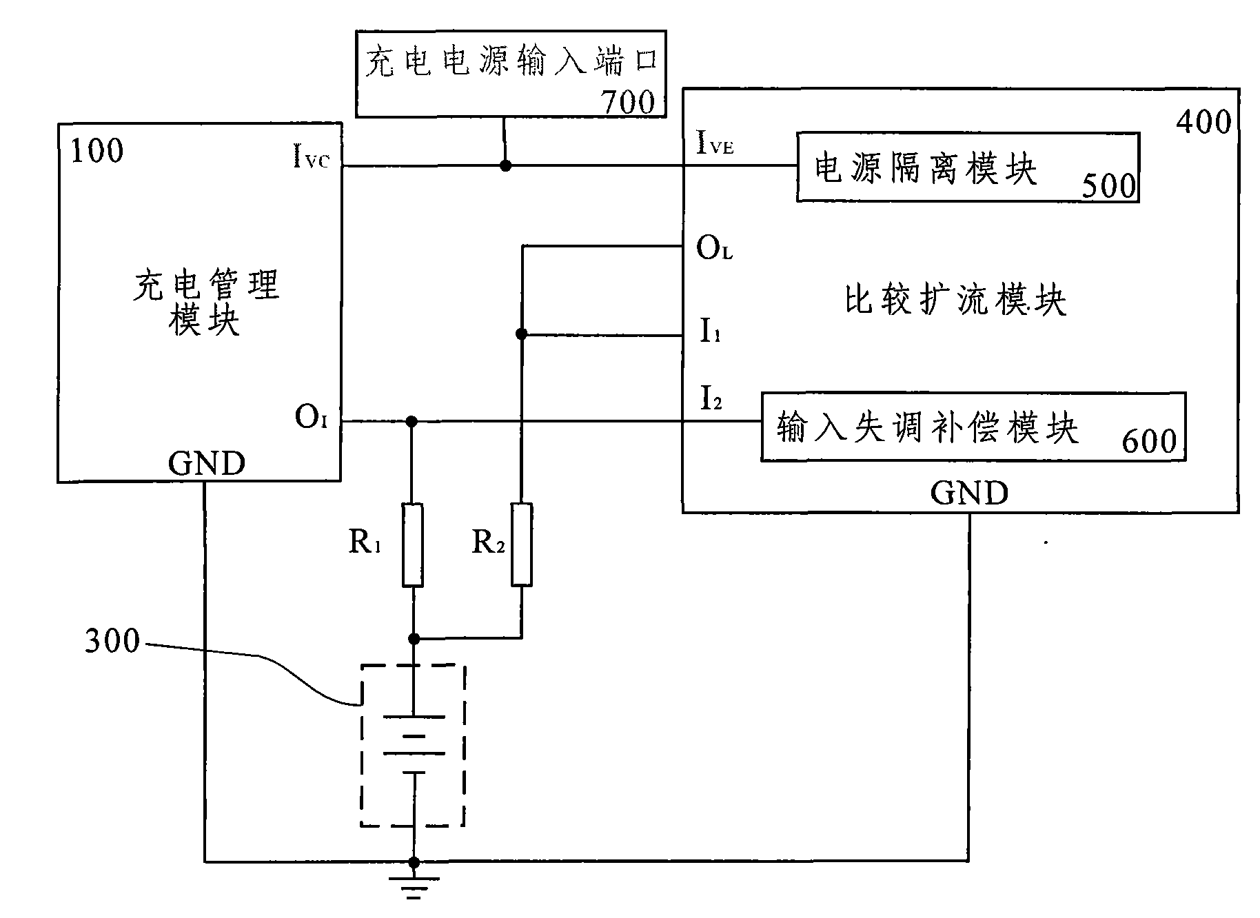
[0027] The invention relates to a current expansion fast charging circuit for handheld electronic devices, such as figure 1 As shown, it includes a charging management module 100 integrated in the main chip of the handheld electronic device or built separately, and a rechargeable battery 300. The charging management module 100 includes a charging power input port 1 VC and charging current output port O I . In particular, also includes the basic charge current sense resistor R 1 , Expansion charging current sampling resistor R 2 And compare the expansion module 400; The comparison expansion module 400 includes the drive power input port 1 VE , the first comparison input port I 1 , the second comparison input port I 2 and expander output port O L ; The basic charging current sampling resistor R 1 The resistance value is greater than the expansio...


PUM


Abstract

A current amplification quick charge circuit used for a hand-hold electronic device comprises a charge management module which is integrated inside a master chip of the hand-hold electronic device orembedded independently, and a rechargeable battery, particularly comprises a basic charging current sampling resistor, a current amplification charging current sampling resistor and a comparation current amplification module; and when the charge management module charges the rechargeable battery, the comparation current amplification module outputs the amplified current from a current amplificaiton output port according to the voltage difference between two comparing input ports. The current amplification quick charge circuit has simple structure, occupies small space of a printed circuit board, greatly improves the practical charging current to the rechargeable battery according to proportion by the two sampling resistors and the comparation current amplification module, improves chargingspeed, satisfies the charging requirement to high-capacity rechargeable batteries, simultaneously keeps the charge management module to conduct three-stage charge, namely, low current precharge stage, constant current charge stage and constant voltage charge stage, to the rechargeable battery, and is beneficial to maintaining the service life of the rechargeable battery.

Description

technical field [0001] The invention relates to a charging device for a rechargeable battery, in particular to a current expansion charging circuit suitable for a charging management module of a handheld electronic device. Background technique [0002] With the rapid development of multimedia technology, Bluetooth technology, wireless network technology, etc., a variety of handheld electronic devices have appeared on the market, including Internet radio, Bluetooth hands-free devices, portable media players, mobile communication terminals, global positioning system GPS, handheld Instruments and PDAs. Generally, the handheld electronic devices have a built-in rechargeable battery as a power source; in order to cooperate with the reasonable charging of the battery, the handheld electronic device is also equipped with a charging management module separately or integrated in the main chip. In order to meet the requirements of miniaturization and portability, the space provided b...

Claims


Application Information

Patent Timeline
Patent Type & Authority Applications(China)
IPC IPC(8): H02J7/00
Inventor 郑伟伟
Owner SUNWODA ELECTRONICS
Why Eureka
Try Eureka