
High-altitude long-span roofing pipe truss installation method

An installation method and technology of pipe trusses, which are applied in the directions of construction, building structure, and building materials processing, etc., can solve problems such as difficult construction, large spans, and heavy weight of installed pipe trusses, so as to improve construction quality and ensure construction safety , to ensure the effect of construction progress

Inactive Publication Date: 2010-03-10
CHINA METALLURGICAL CONSTR ENG GRP
View PDF0 Cites 32 Cited by
  • Summary
  • Abstract
  • Description
  • Claims
  • Application Information

AI Technical Summary

Problems solved by technology

[0002] At present, the installation of low-altitude and small-span roof pipe trusses is mostly directly installed by cranes, but for roofs with a span of tens of meters or even hundreds of meters, due to the small turning radius of the crane, the construction period is tight, and the construction site is relatively narrow. The overall assembly site of the truss cannot be completed by using a super-large crawler crane, so it must be completed with the help of a mobile tower crane
[0003] For the installation of pipe trusses with heavy weight, large cross-section, large span, and a height of up to 100 meters on the roof, and the construction site is narrow, it is difficult and costly to use a large crawler crane in the narrow construction site area.
If the high-altitude sliding construction method is used to install the pipe truss, it is necessary to add embedded parts on the two columns, but it is easy to generate additional construction force when sliding, and the frame column of the ear room also needs to add embedded parts, which will also cause additional construction. At the same time, it is very difficult to install and disassemble the supporting truss, the construction period is long, the crane cannot cover it, and the installation of the truss is relatively large

Method used


Image

  • High-altitude long-span roofing pipe truss installation method

Examples


Embodiment Construction

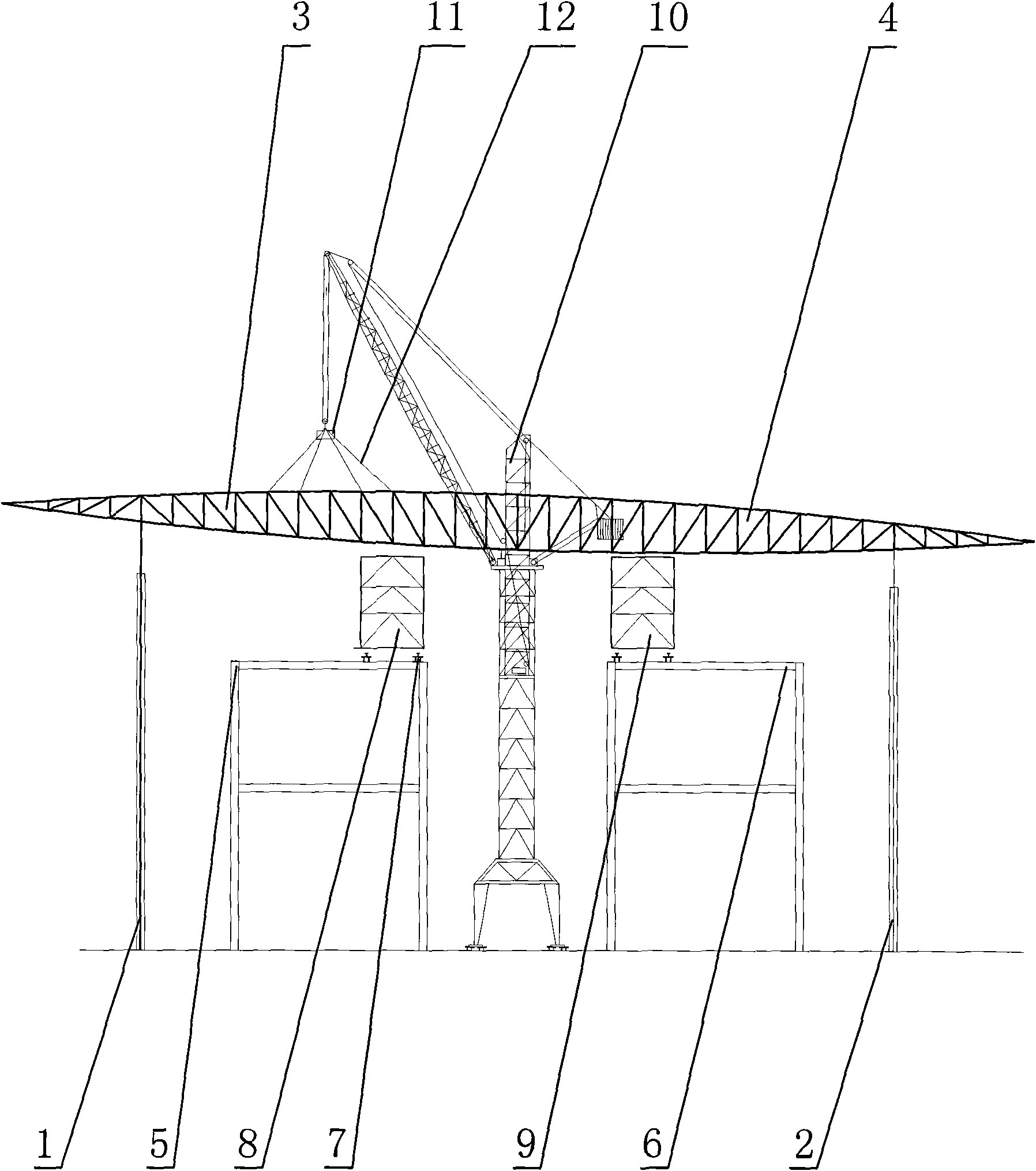
[0017] Accompanying drawing is the structural representation of the present invention, as shown in the figure: the installation method of high-altitude large-span roof pipe truss comprises the following steps:

[0018] a. The pipe trusses are assembled on the ground. The number of pipe trusses is mainly determined according to the length of the roof. If a pipe truss is installed at an interval of 12m or 9m; and each pipe truss is composed of several sections, it is mainly based on the span of the roof and the mobile tower crane plane position and rated lifting capacity, the span of the pipe truss in this embodiment is the distance (such as 96m) between the left reinforced concrete column 1 and the right reinforced concrete column 2, and the mobile tower crane 10 selects TQ1000 / 60 mobile tower crane, the mobile tower crane The radius of gyration is 24m, so the pipe truss in this embodiment is composed of two pipe trusses (namely, the left pipe truss 3 and the right pipe truss 4)...


PUM


Abstract

The invention discloses a high-altitude long-span roofing pipe truss installation method which comprises the following steps: firstly, assembling pipe trusses on the ground, then arranging a construction platform beam at the high-altitude assembling pipe truss; adopting a movable tower crane to hoist the pipe trusses, and hoisting two sections of pipe trusses on an assembling bracket and a reinforced concrete stand column; finally, conducting high-altitude joint, assembly and welding on the pipe trusses; and after passing welding inspection, moving the assembling bracket to the next axis and conducting installation of the next pipe trusses. The high-altitude long-span roofing pipe truss installation method adopts ground segment assembly, movable tower crane hoisting and the high-altitude joint welding method, not only improves construction quality, guarantees construction process and safety, and simultaneously reduces construction cost.

Description

technical field [0001] The invention relates to a roof truss installation method, in particular to a high-altitude long-span roof pipe truss installation method. Background technique [0002] At present, the installation of low-altitude and small-span roof pipe trusses is mostly directly installed by cranes, but for roofs with a span of tens of meters or even hundreds of meters, due to the small turning radius of the crane, the construction period is tight, and the construction site is relatively narrow. The overall assembly site of the truss cannot be completed with a super large crawler crane, so it must be completed with the help of a mobile tower crane. [0003] For the installation of pipe trusses with heavy weight, large cross-section, large span, and a height of up to 100 meters on the roof, and the construction site is narrow, it is difficult and costly to use a large crawler crane in the narrow construction site area. If the high-altitude sliding construction metho...

Claims


Application Information

Patent Timeline
IPC IPC(8): E04G21/14
Inventor 徐国友邱文波周革文
Owner CHINA METALLURGICAL CONSTR ENG GRP
Learn More