Monopole radio frequency antenna

A radio frequency antenna, a single-stage technology, applied in the field of radio frequency devices, can solve the problems of increasing the area of ​​the radio frequency system, increasing the design of the feeder line of the electronic system, and it is difficult to meet the system design requirements of low power consumption, and achieve the effect of enriching the dispersion characteristics

Inactive Publication Date: 2010-03-10
深圳大鹏光启科技有限公司
View PDF0 Cites 154 Cited by
  • Summary
  • Abstract
  • Description
  • Claims
  • Application Information

AI Technical Summary

Problems solved by technology

However, the impedance matching network additionally increases the feeder design of the electronic system and increases the area of ​​the radio frequency system.

Method used


Image

  • Monopole radio frequency antenna
  • Monopole radio frequency antenna
  • Monopole radio frequency antenna

Examples


Embodiment Construction

[0037] The present invention will be described in further detail below in conjunction with accompanying drawing and preferred embodiment:

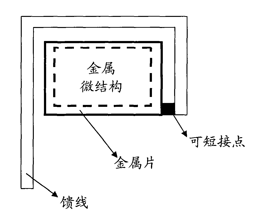
[0038] Such as figure 1 As shown, it is a structural schematic diagram of Embodiment 1 of the antenna of the present invention, including a metal sheet engraved with a metal microstructure, a feeder, and a medium. In this embodiment, the medium used to place the metal sheet and the feeder is air, and the metal sheet Located on the same plane as the feeder, the metal sheet is provided with a short-circuit point, and the metal sheet and the feeder are connected through the short-circuit point.

[0039] Among them, the feeder can generally be regarded as a pin of the small antenna of the RF chip, which is fed in with a standard 50 ohm impedance. The feeding method of the feeder can be capacitive coupling or inductive coupling. When there is a contact, the feeder is fed into the metal sheet by capacitive coupling; when there is a short-circui...


PUM


Abstract

The invention discloses a monopole radio frequency antenna comprising a metal sheet, a feeder line and a medium for the placement of the metal sheet and the feeder line. The feeder line is fed into the metal sheet through a coupling mode. The monopole radio frequency antenna has the advantages of small size, simple machining, low cost, high utilization rate of an antenna radiation area, easy matching design of a multimode antenna, high interference resisting capability and the like.

Description

technical field [0001] The invention relates to the technical field of wireless radio frequency devices, in particular to a single-stage radio frequency antenna. Background technique [0002] With the high development of semiconductor technology, higher and higher requirements are put forward for the integration of today's electronic systems, and the miniaturization of devices has become a technical issue of great concern to the entire industry. However, unlike the development of IC chips following "Moore's Law", radio frequency modules, another important component of electronic systems, face the difficult technical challenge of device miniaturization. The radio frequency module mainly includes main components such as frequency mixing, power amplifier, filter, radio frequency signal transmission, matching network and antenna. Among them, the antenna is the radiating unit and receiving device of the final radio frequency signal, and its working characteristics will directly ...

Claims


Application Information

Patent Timeline
IPC IPC(8): H01Q9/30
Inventor 刘波
Owner 深圳大鹏光启科技有限公司
Why Eureka
Try Eureka