Integrated silt loosening and sucking device for removing silt

A dredging device and sludge technology, which is applied in the direction of mechanically driven excavators/dredgers, etc., can solve the problems of difficult extraction of hardened mud, high price of equipment, and difficult transportation, and achieve light weight, reasonable and simple overall structure, and easy The effect of the operation

Inactive Publication Date: 2010-03-17
NANJING HYDRAULIC RES INST THE MINISTRY OF WATER RESOURCES THE MINIST
View PDF0 Cites 11 Cited by
  • Summary
  • Abstract
  • Description
  • Claims
  • Application Information

AI Technical Summary

Problems solved by technology

[0003] There are three existing technical structures for dredging small rivers both at home and abroad. One is to drain the water in the river with a water pump after damming, and then use a mud pump to pump the mud to the bank for sedimentation. The mud is not easy to extract; the second is to use the grab excavator to work on the river embankment to dig out the silt in the river channel, stack it on the spot or transport it away by vehicle and boat, but it is not easy to work due to the width of the river channel and embankment; the third is to use water The lower dredging machine is characterized in that the whole machine pumps the mud to the bank for sedimentation while walking in the water. It can work with water, but it is not easy to control, the price of the machine is high, and it is difficult to carry after the operation is completed.

Method used


Image

  • Integrated silt loosening and sucking device for removing silt
  • Integrated silt loosening and sucking device for removing silt
  • Integrated silt loosening and sucking device for removing silt

Examples


Embodiment Construction

[0024] Below in conjunction with accompanying drawing, the present invention is described in detail:

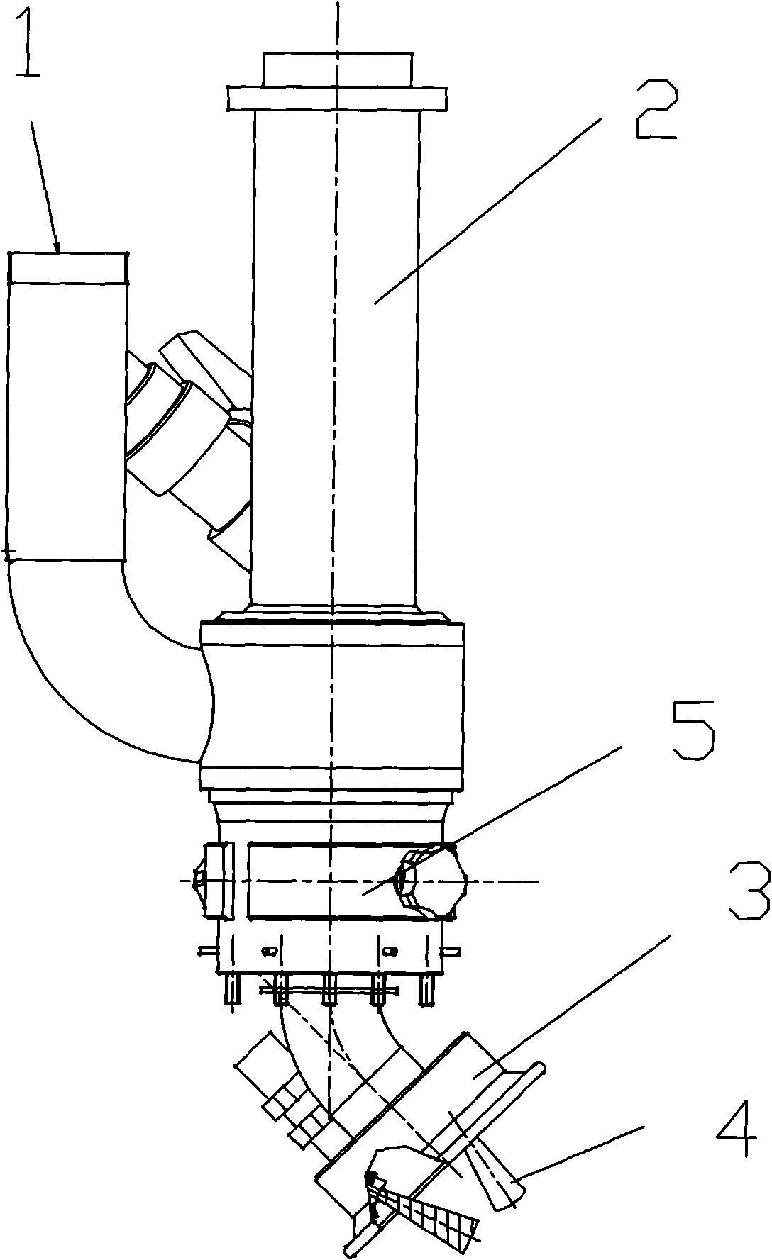
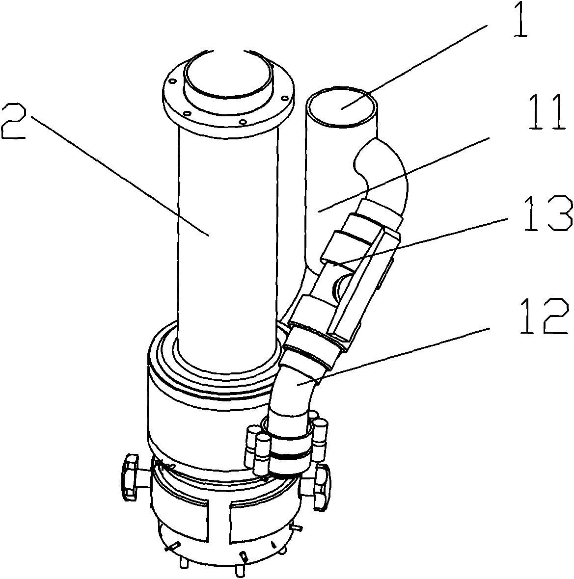
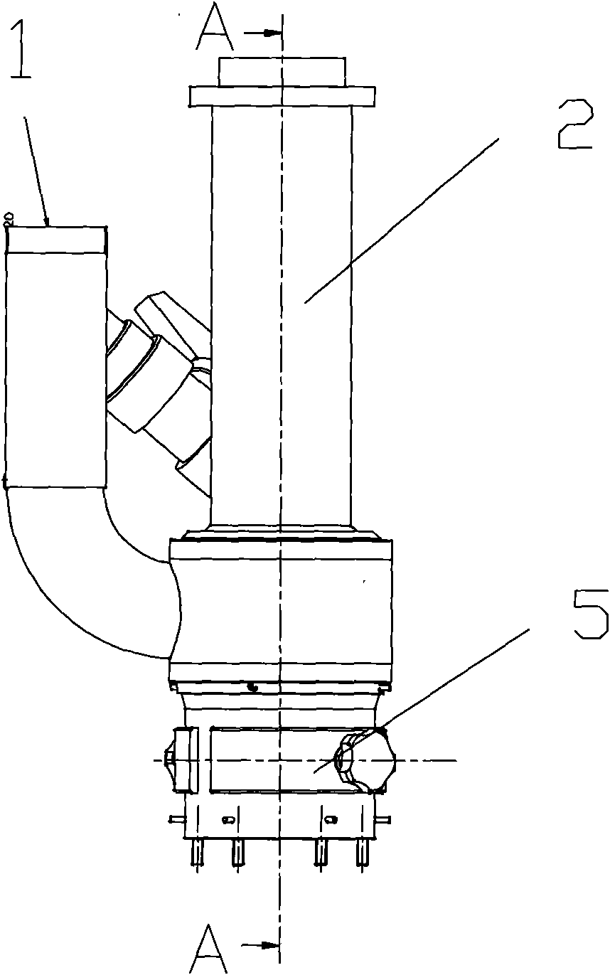
[0025] like figure 1 , figure 2 As shown, the sludge loosening and suction integrated dredging device of the present invention consists of a high-pressure water inlet pipe 1, a high-pressure water nozzle 4, a sludge suction head cover 3, a mud outflow pipe 2, and a negative pressure regulating valve 5. The high-pressure water inlet pipe 1 has two outlets. , one outlet 11 is connected to the high-pressure water nozzle 4 on the mud suction head cover 3, which is used for ejecting the loose and compacted mud of high-pressure water, and the other outlet 12 is connected to the high-pressure water flow channel 21 in the mud outlet pipe 2, and the high-pressure water flow channel The outlet of 21 is consistent with the outflow direction of the mud. When the high-pressure water flows in the reverse direction through the high-pressure water flow channel, a negative pressure cavity 2...


PUM


Abstract

The invention discloses an integrated silt loosening and sucking device for removing silt, which comprises a high-pressure water inlet pipe, a high-pressure water nozzle, a silt suction head cap and asilt outflow pipeline, wherein the silt suction head cap is connected with one end of the silt outflow pipeline; the high-pressure water inlet pipe comprises a first water outlet and a second water outlet; a high-pressure water flow passage is arranged in the silt outflow pipeline; the inlet of the high-pressure water flow passage is connected with the second water outlet; the outlet of the high-pressure water flow passage is communicated with the inner cavity of the silt outflow pipeline and is in the same direction of the silt outflow pipeline; the high-pressure water nozzle is arranged onthe silt suction head cap; and the water inlet of the high-pressure water nozzle is connected with the first water outlet of the high-pressure water inlet pipe. Compared with the prior art, the devicehas the advantages of reasonable and simple integral structure, light weight, convenient transportation and no movable components, has the functions of modularized unit combination and the like and is free of maintenance; the specification and the performance of the device conform to the dredging standard; the device is peculiar in structural design, and can regulate the optimal flow rates for suction and spraying according to the characteristics of the silt; the device can drain flow smoothly; and the pipe cavity is not easily blocked.

Description

technical field [0001] The invention relates to the technical field of river dredging, in particular to a dredging device used for river dredging silt. Background technique [0002] There are many rivers and lakes in my country's water network area, and the water system is developed, but the problem of river sedimentation is becoming more and more prominent. Excessive sedimentation in the river channel will make the effective depth of the river channel shallow, the water body capacity and drainage and irrigation capacity will decrease, the source pollution of the water body will increase, the water ecological environment will deteriorate, the comprehensive agricultural production capacity will be weakened, and the production and life of the people will be affected. Dredging is the most effective engineering measure for rural water resources, water ecology and water environment protection. [0003] There are three types of dredging technology structures for small river chann...

Claims


Application Information

Patent Timeline
Patent Type & Authority Applications(China)
IPC IPC(8): E02F3/88E02F3/90
Inventor 孙金华李云樊宝康罗勇骆少泽葛九峰孙凤
Owner NANJING HYDRAULIC RES INST THE MINISTRY OF WATER RESOURCES THE MINIST
Why Eureka
Try Eureka