Method for detecting measurement stability of tester tables

A technology for testing and testing machines, which is applied in semiconductor/solid-state device testing/measurement, electrical components, semiconductor/solid-state device manufacturing, etc. It can solve the problems of relatively large difference in oxide thickness, deviation of metal layer thickness, and difference in measurement results. Larger problems, to achieve the effect of easy observation and judgment, simple and effective operation

Inactive Publication Date: 2011-06-15
SEMICON MFG INT (SHANGHAI) CORP
View PDF3 Cites 0 Cited by
  • Summary
  • Abstract
  • Description
  • Claims
  • Application Information

AI Technical Summary

Problems solved by technology

Since the copper metal layer 120 is exposed to the air, when the microsecond ultrasonic laser sonar 150 emits a laser pulse wave and reaches the surface of the copper metal layer 120, the surface of the copper metal layer 120 will be thermally oxidized to form a copper oxide cover, due to the oxidation of different points The degree is not the same, resulting in poor flatness of the copper metal layer 120 surface, forming some uneven areas, especially after more than one measurement over a long period of time, the copper metal layer 120 on the surface of the control sheet is heated more than once and for a long time Exposure to the air, the degree of oxidation suffered by the copper metal layer 120 is relatively serious, and the oxide thickness difference at different points is relatively large. When measuring, the propagation speed of the sound wave in the copper metal layer 120 and its oxide is inconsistent, so the influence The echo time of different points is changed, thus causing inconsistent results of measuring the thickness value of the copper metal layer 120. The thickness value of the metal layer obtained according to this method itself has a large deviation. Please refer to figure 2 , figure 2 Shown is a schematic diagram of the results of the detection and testing machine in the prior art. It can be seen from the figure that after a long time, the obtained measurement results are quite different from each other, so it cannot be used to judge the performance of the microsecond ultrasonic laser sonar test device. Whether the measurement stability is within the acceptable range

Method used


Image

  • Method for detecting measurement stability of tester tables
  • Method for detecting measurement stability of tester tables
  • Method for detecting measurement stability of tester tables

Examples


Embodiment Construction

[0027] In order to better understand the technical content of the present invention, specific embodiments are given together with the attached drawings for description as follows.

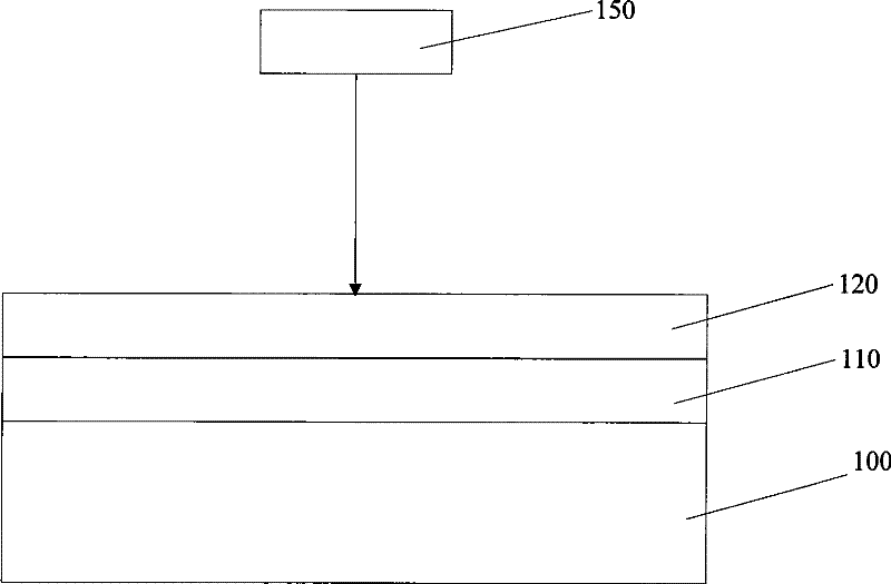
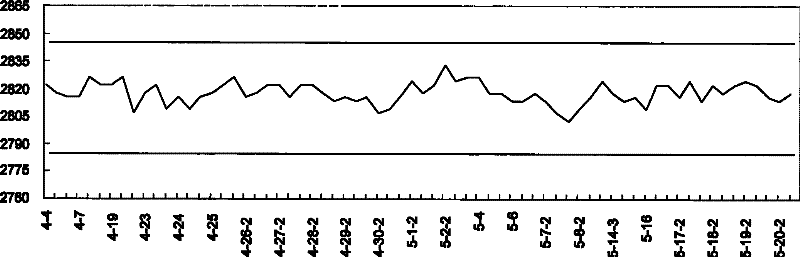
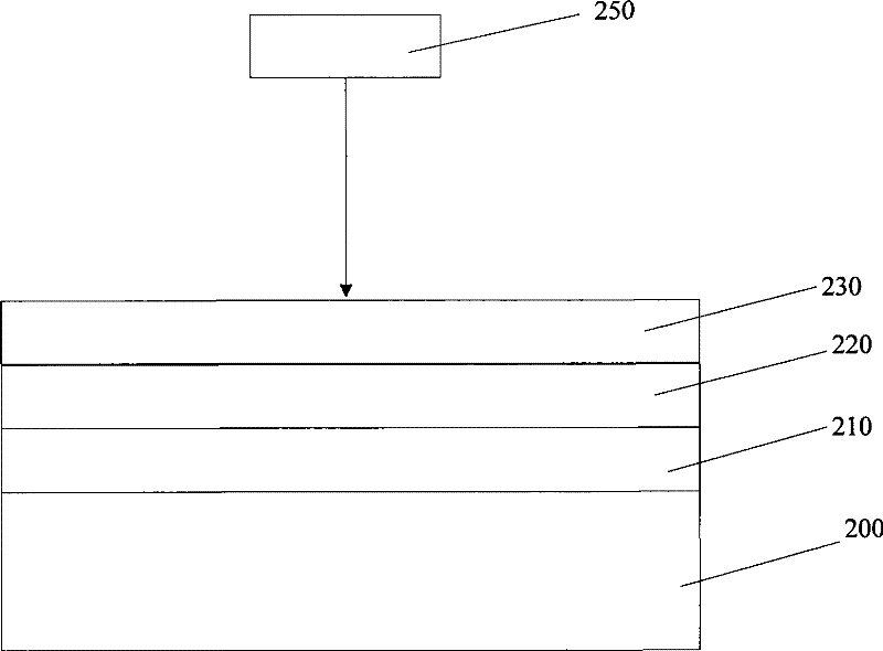
[0028] Please refer to image 3 , image 3 Shown is a schematic diagram of a method for detecting and testing a testing machine in a preferred embodiment of the present invention. The method for detecting and measuring the stability of the testing machine proposed by the present invention is aimed at testing devices such as microsecond ultrasonic laser sonar. First, a control chip is provided as a test wafer, and an oxide layer is formed on the semiconductor substrate 200 of the control chip. 210, the composition of the oxide layer 210 is SO 2 The oxide layer 210 may have a thickness of 1000 angstroms to 4000 angstroms. The purpose of forming the oxide layer 210 is to prevent the copper ions of the copper metal layer 220 electroplated from diffusing into the semiconductor substrate 200 during the...


PUM


Abstract

The invention proposes a method for detecting measurement stability of tester tables. The method comprises the following steps: providing a control wafer serving as a test wafer and electroplating a semiconductor substrate with a metal layer; depositing an anti-oxidation layer on the metal layer; utilizing a tester table to measure the thickness of the metal layer of the control wafer more than once; and judging whether the measurement stability of the tester table is within an acceptable range according to more than one metal-layer thicknesses obtained through measurement. The method obtainsa standard deviation value by calculating the more than one metal-layer thicknesses obtained through measurement, and can accurately judge whether the measurement stability of the tester table is within the acceptable range according to the obtained standard deviation value. The method has the advantages of simple effective operation and results easy to observe and judge.

Description

technical field [0001] The invention relates to a method for detecting a test machine, and in particular to a method for detecting the measurement stability of a test machine in a semiconductor process. Background technique [0002] In the process used to make copper wire interconnect structures, there may be non-uniformity in the deposition of copper metal and the grinding rate. If not carefully controlled, it will result in uneven thickness or unwanted residue on the surface of the wafer. substance. Varying thickness will affect the resistance, which will lead to the failure of the component or the reduction of the overall performance. Substances remaining inside may cause short circuits between wires, which can also lead to component failure and yield loss. There is a non-destructive way to directly measure the thickness of sub-micron wire array structures in order to control the deposition of copper metal and the removal rate. [0003] This method is the use of micros...

Claims


Application Information

Patent Timeline
Patent Type & Authority Patents(China)
IPC IPC(8): H01L21/00H01L21/66
Inventor 张振华方明海吕秋玲
Owner SEMICON MFG INT (SHANGHAI) CORP
Why Eureka
Try Eureka