Power supply system

A power supply system and electric energy technology, which is applied in the system, electrical components, fixed capacitor electrodes, etc. for storing electric energy, and can solve the problems of fast discharge speed, easy damage, and aging of batteries.

Inactive Publication Date: 2010-03-17
LITE ON TECH CORP
View PDF0 Cites 2 Cited by
  • Summary
  • Abstract
  • Description
  • Claims
  • Application Information

AI Technical Summary

Problems solved by technology

[0008] Generally speaking, although the capacitor is relatively simple in manufacturing process, its energy storage capacity is relatively small due to its low energy storage density, and it can only be used as short-term energy storage.
The traditional battery mainly uses chemical energy to store energy, so its energy storage density is significantly better than that of general capacitors, and it can be applied to various power supply devices. However, the disadvantage is: the instantaneous power output it can generate It will be limited by the chemical reaction rate, so it cannot charge and discharge quickly or perform high power output, and the number of charge and discharge is limited, and it is easy to cause various problems when overcharged; for example: the batteries currently used, although advertised as reusable , but still has its lifetime limit
In the case of repeated charging and discharging or long-term non-use, the capacity of the battery will decrease and it will be easily damaged. The reason is that the battery uses chemical energy to convert into electrical energy. When the activity of all the compounds is used up or nearly used up, new chemical reactions can no longer be carried out, which leads to the aging of the battery and the end of its service life
The supercapacitor is a component between the battery and the capacitor, also known as the electrical double-layer capacitor (Electrical Double-Layer Capacitor), because it uses part of the physical energy storage and part of the chemical energy storage structure at the same time, so it has more energy than ordinary capacitors. Large capacity, but its disadvantages are: due to the chemical characteristics of the chemical material, it is easy to have th

Method used


Image

  • Power supply system
  • Power supply system
  • Power supply system

Examples


Embodiment Construction

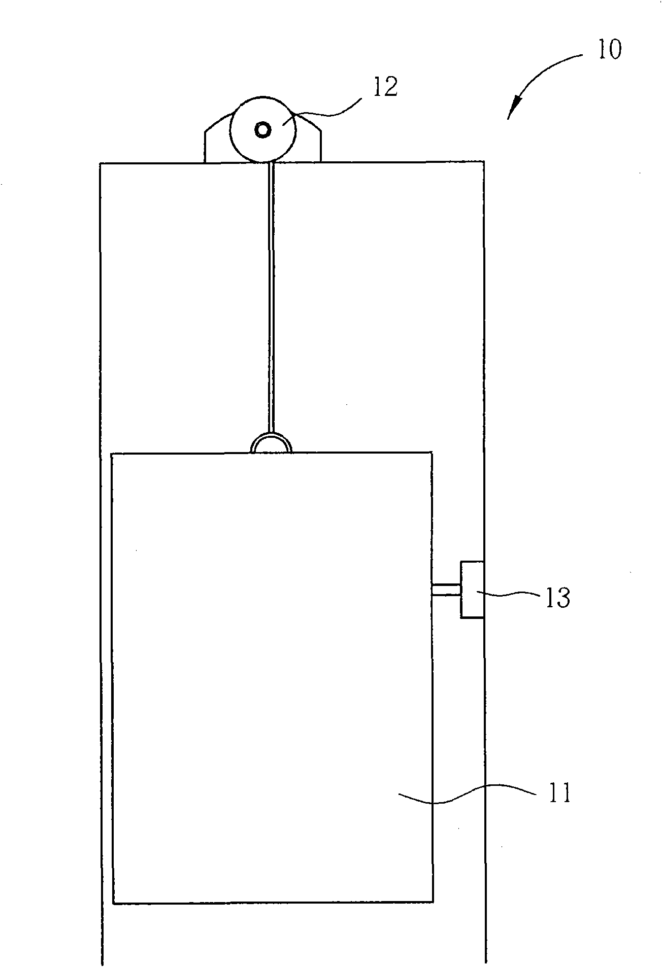
[0045] The main feature of the present invention is to provide a power supply system comprising an energy storage device composed of one or more magnetic capacitors. The power supply system can use the large amount of electric energy wasted in known lifting equipment through the high storage capacity of the magnetic capacitors. Recycling and storage of energy capacity to achieve the purpose of saving energy reuse and reducing load electric energy costs.

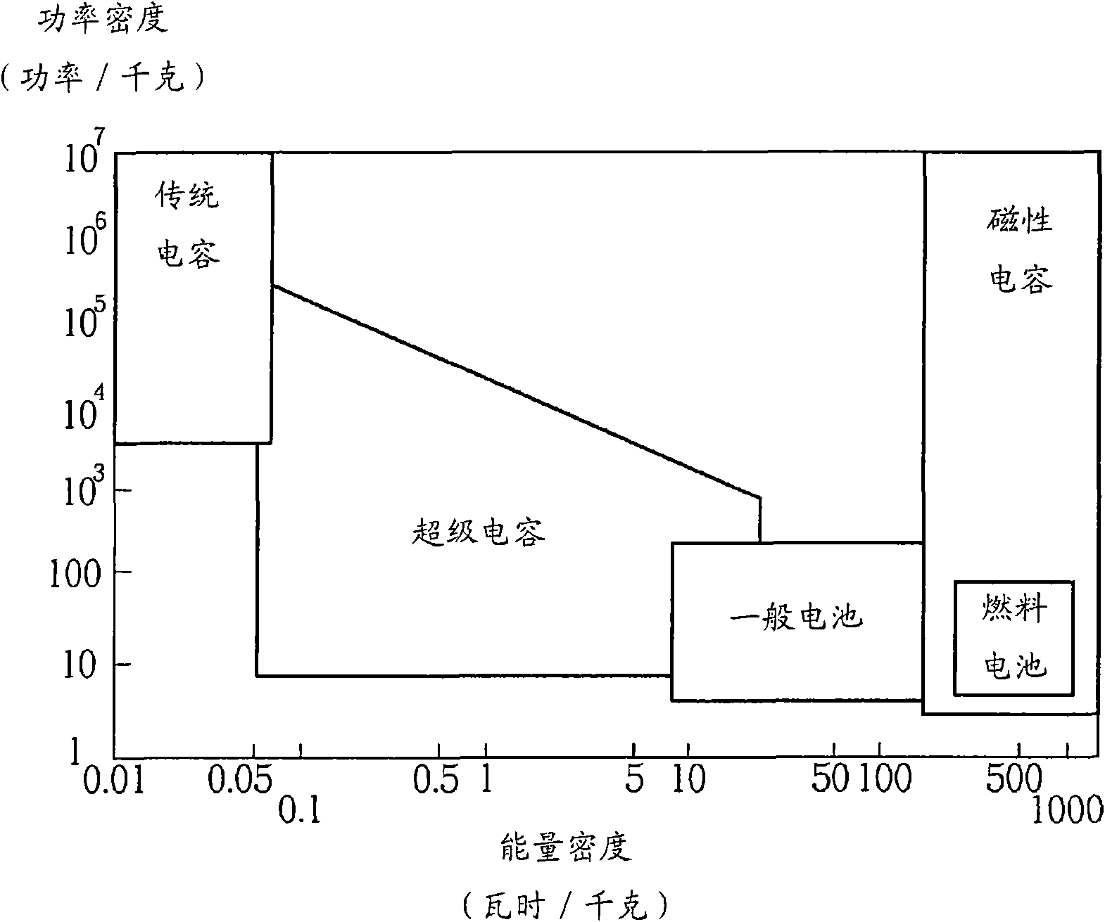
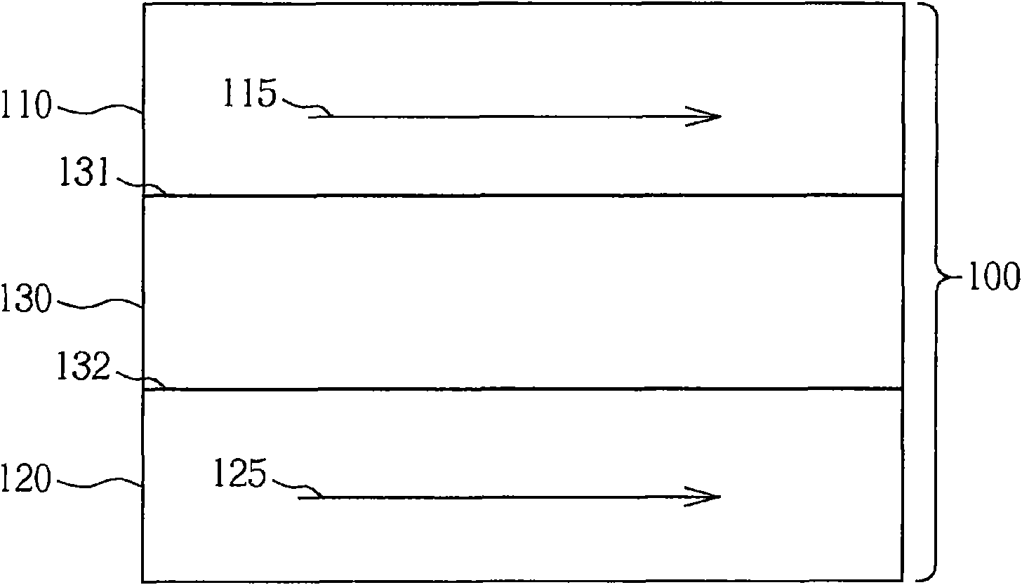
[0046] Compared with traditional electric energy storage devices (such as batteries or capacitors or supercapacitors), the magnetic capacitor disclosed in the present invention can store charges at a higher density through the magnetic field formed at the upper and lower electrodes, so that in lifting equipment , the possibility of recovering energy can be achieved only by paying an additional weight and hardware cost within an acceptable range.

[0047] The principle and operation details of the magnetic capacitor of the pre...


PUM


Abstract

The invention provides a power supply system comprising an energy conversion device and an energy storing device. The energy conversion device is used for converting the potential energy difference ofa bearing structure into an electric energy when the bearing structure of a lifting appliance falls. The energy storing device is coupled to the energy conversion device and is used for storing the electric energy generated by the energy conversion device when the bearing structure falls. The energy storing device comprises at least one magnetic capacitance module which comprises at least one magnetic capacitor. Since the magnetic capacitor module is added to the system, the electric energy obtained from the energy conversion device by converting the potential energy difference without changing the main structure and design of the traditional lifting appliance, and the electric energy is provided to the lifting appliance for rising , thereby greatly increasing the reuse efficiency of theenergy sources so as to save the energy resources.

Description

technical field [0001] The invention relates to a power supply system, in particular to a power supply system used in a lifting device, which can recover part of the potential energy released by the lifting device, convert the part of the potential energy into electric energy for reuse, and achieve the effect of energy saving. Background technique [0002] Lifting equipment is an indispensable part of today's types of building structures, especially in cities where building land is generally insufficient, and buildings have to increase their height to achieve a higher volume ratio. Therefore, whether it is carrying people or objects, all kinds of lifting equipment can be seen everywhere in daily life, and the operation of lifting equipment consumes energy is inevitable, so the following will briefly describe the operation and energy consumption of known lifting equipment relationship. [0003] Please refer to figure 1 , figure 1 is a schematic diagram of a known lifting d...

Claims


Application Information

Patent Timeline
IPC IPC(8): H02J15/00H01G4/008
Inventor 许跃腾
Owner LITE ON TECH CORP
Why Eureka
Try Eureka