Production method and device of electronic components

A technology for producing electronic parts and rolls, which is applied in the field of producing winding electronic parts, can solve the problems such as the difficulty in improving the electrical characteristics of electrolytic capacitors of electronic parts, and achieve the effect of reducing resistance

Inactive Publication Date: 2010-03-24
JCC ENG
View PDF0 Cites 8 Cited by
  • Summary
  • Abstract
  • Description
  • Claims
  • Application Information

AI Technical Summary

Problems solved by technology

Therefore, it has been difficult to improve the electrical charac

Method used


Image

  • Production method and device of electronic components
  • Production method and device of electronic components
  • Production method and device of electronic components

Examples


Embodiment Construction

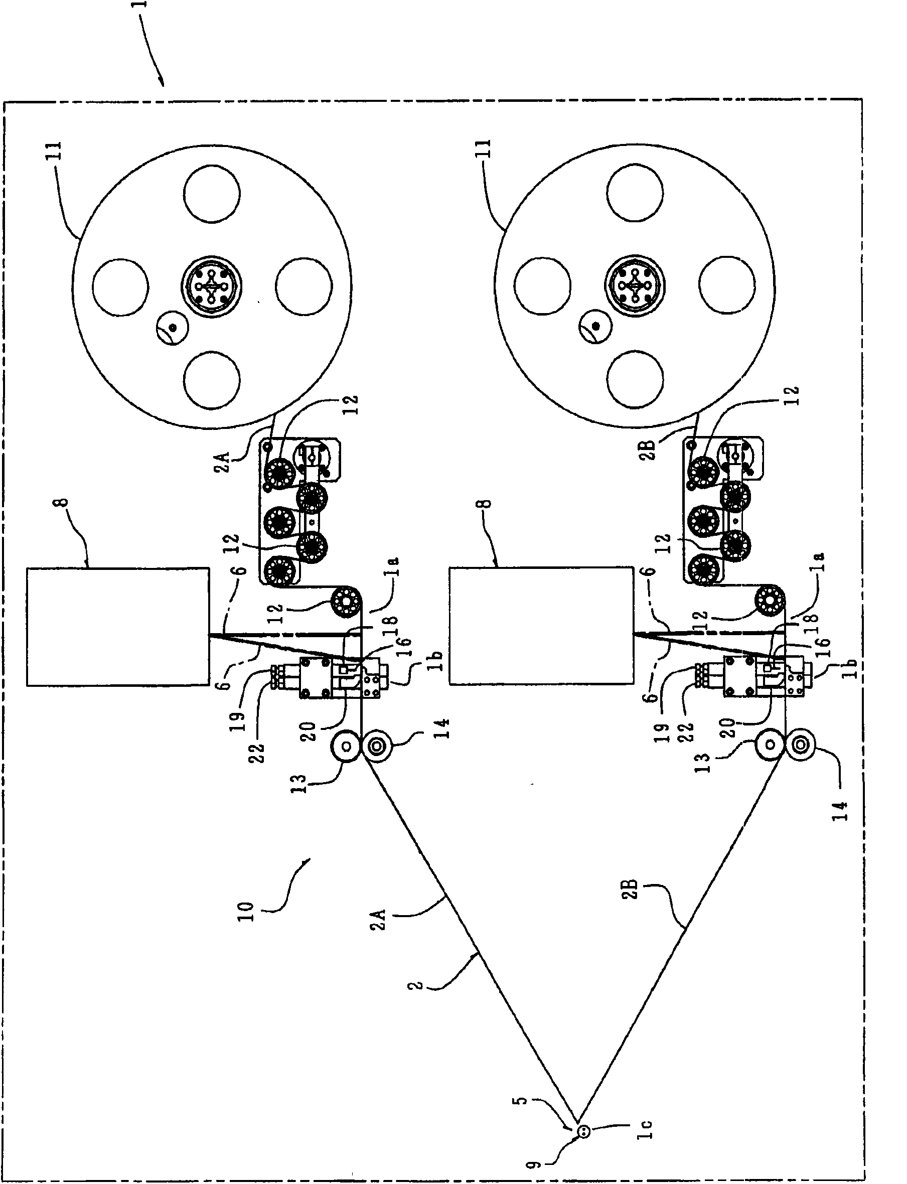
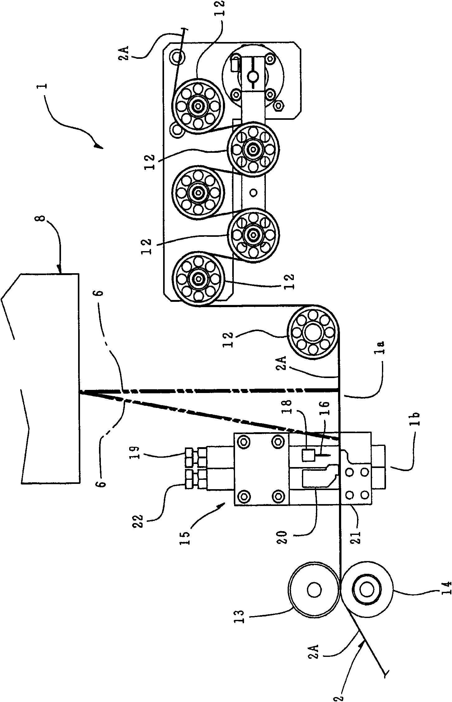
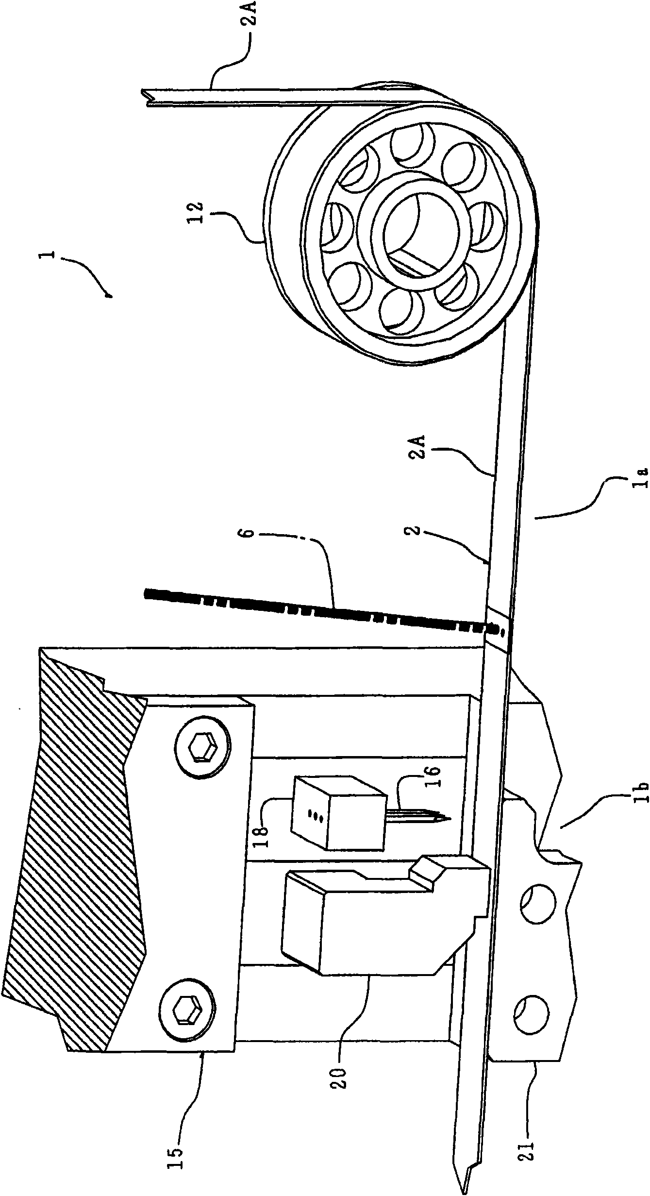
[0050] The present invention will be described in detail below with reference to the accompanying drawings. refer to Figure 1-5 , as an example, an apparatus 1 for producing an electronic part as a wound-type electrolytic capacitor 5 is equipped with a laser irradiation apparatus 8 for irradiating a laser beam to an electrode foil 2 to peel and remove an etching layer or coating from the electrode foil 2. layer (hereinafter referred to as "forming film 2a") ( Figure 6-8 ) for while the electronic parts production apparatus 1 is conveying a plurality of electrode foils 2 (2A, 2B) and a plurality of release papers 3 (3A, 3B) and winding the electrode foils 2 and the release paper 3 so as to wrap the lead terminals 4 ( 4A, 4B) while the joint 4a of the electrode foil 2 is attached to the electrode foil 2, before the electrode foil 2 is pierced with a piercing needle to attach the joint of the lead terminal, a hole is formed in the electrode foil 2 or a hole is formed in the el...


PUM


Abstract

The present invention relates to a production method and device of electronic components. The invention provides a production method of electronic components and a device thereof, in particular provide a production method and devices for winding type electronic components (particularly electrolytic capacitors), wherein the traditional tools are replaced and a laser radiation device is used to radiate the laser to an electrode foil, in order to isolate and remove an etching layer or a coating layer from the electrode foil, and holes are formed in the electrode foil, then a groove is formed in ahorizontal side facing to the electrode foil. According to the invention, it is possible to optionally set the shape of the electrode foil from which the etching layer or the coating layer is removed, and to optionally set the shapes of the holes and the groove. As a result, it is possible to expand a contacting area between a joint of the lead wire terminal and metal of the electrode foil.

Description

technical field [0001] The present invention relates to a kind of electronic component production method and its device, more particularly relate to be used for producing the concrete method and its device of winding type (rolled up) electronic component (particularly electrolytic capacitor), wherein, replace traditional tool and A laser is provided to radiate a laser beam to the electrode foil before a process of processing the electrode foil using a piercing needle to connect a tab of a lead terminal to the electrode foil, thereby separating and The etch layer or coating is removed and holes are formed in the electrode foil, followed by grooves in laterally opposite sides of the electrode foil. According to the present invention, the shape of the region of the electrode foil where the etching layer or coating is separated can be optionally set, and the shape of the holes and grooves can also be optionally set. As a result, the contact area between the joint of the lead term...

Claims


Application Information

Patent Timeline
IPC IPC(8): H01G4/32H01G4/228H01G9/00H01G9/008H01G13/00H01G9/048H01G13/02
CPCH01G11/26H01G11/30H01G13/02H01G13/06
Inventor 田中浩司
Owner JCC ENG
Why Eureka
Try Eureka