Submersed type inspection well and construction method thereof

A construction method and inspection well technology, applied to waterway systems, drainage structures, water supply devices, etc., can solve the problems of increasing the number of working wells or receiving wells, increasing the cost of pipe jacking projects, hindering the development of pipe jacking construction technology, etc. The method is simple and convenient, preventing the effect of additional displacement

Inactive Publication Date: 2010-03-31
吴纪东 +1
View PDF0 Cites 25 Cited by
  • Summary
  • Abstract
  • Description
  • Claims
  • Application Information

AI Technical Summary

Problems solved by technology

[0005] If the mechanical pipe jacking project is designed according to the requirements of the outdoor drainage design code (GB50201-2005), according to the above table, the longest distance of the pipe jacking ca

Method used


Image

  • Submersed type inspection well and construction method thereof
  • Submersed type inspection well and construction method thereof
  • Submersed type inspection well and construction method thereof

Examples


Embodiment 1

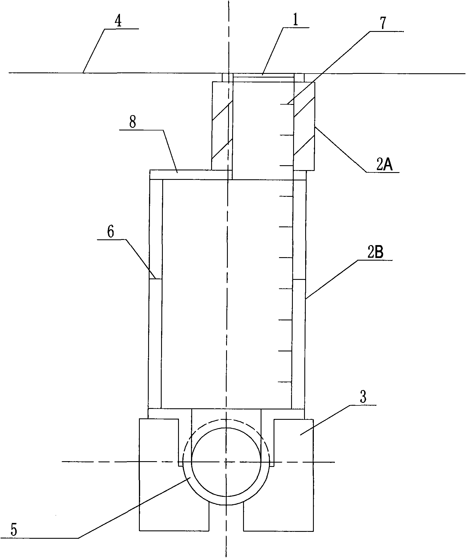
[0037] Such as figure 1 As shown, the immersed tube inspection well of the present invention includes a well cover 1 on the ground and a well shaft 2 below the well cover 1. Below the well shaft 2 is an existing drainage pipe 5. A foundation 3 is poured between the lower end of the well shaft 2 and the drainage pipe 5. The lower end of the wellbore 2 and the upper end of the foundation 3 are poured into one body, the diameter of the foundation 3 ≥ the outer diameter of the wellbore + 0.1 meters, the bottom of the foundation 3 is located 0.3 meters below the skin of the existing drainage pipe 5, and the bottom of the foundation 3 extends inward to the existing drainage pipe 1 / 3 of the 5 diameter. Among them, the wellbore 2 consists of upper and lower parts. The upper shaft 2A extends downward from the road surface to the subgrade elevation (usually 2.5 meters below the road surface) and its cross section is smaller than that of the lower shaft. The lower shaft 2B adopts "F" typ...

Embodiment 2

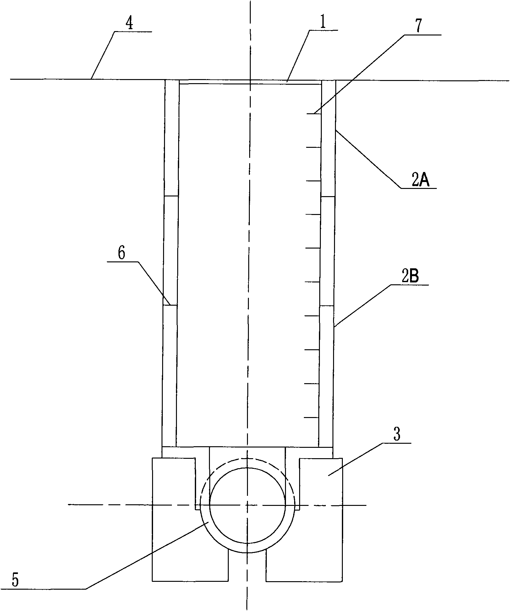
[0054] Such as figure 2 As shown, the difference between the present embodiment and the first embodiment is that the wellbore is not divided into the upper section wellbore and the lower section wellbore (adopting "F" type reinforced concrete pipe), so there is no need to set the wellbore cover plate 8; the stage (4 ); Step 4 of stage (2) should repeat the process of connecting the wellbore at last to connect the wellbore to the road surface.

[0055] The wellbore 2 in this embodiment is not divided into the upper section and the lower section, and should be adopted when there are no other pipelines under the road surface at the construction site, which can simplify the construction process.

[0056] By adopting the structure and construction method of the present invention, it is convenient to adopt the immersed tube construction method to manufacture inspection wells, thereby facilitating long-distance pipe jacking construction, developing new prefabricated inspection well ...


PUM


Abstract

The invention discloses a submersed type inspection well which comprises a well cover above the ground as well as a shaft and a well body structure below the well cover, wherein the traditional drainage pipe is arranged below the shaft, a foundation is arranged between the lower end of the shaft and the drainage pipe, and the lower end of the shaft, the upper end of the foundation and the pipe arepoured into a whole; the diameter of the foundation is larger than the outer diameter of the shaft, and the bottom end of the foundation is located below the sheath of the traditional drainage pipe;and the bottom end of the foundation is inwards extended below the traditional drainage pipe. The invention also discloses a construction method for realizing the inspection well, which comprises thefollowing construction stages: (1) placing the inspection well; (2) submersing, joining and measuring the shaft; (3) manufacturing the foundation of the inspection well and communicating the shaft with the traditional drainage pipe; and (4) mounting a shaft cover plate and a ladder. By adopting the structure and the method of the invention, the inspection well is conveniently manufactured by adopting a submersed type construction method so as to be beneficial to carrying out long-distance jacking pipe construction and developing novel prefabricated inspection well structures and convenient for carrying out pipe engineering construction in downtown areas without excavating.

Description

technical field [0001] The invention relates to an immersed tube type inspection well and a construction method thereof. Background technique [0002] Pipe jacking construction is the main construction method of trenchless underground pipeline construction in urban drainage projects. It does not need to excavate the surface layer, and it can cross roads, railways, rivers, ground buildings, underground structures and various underground pipelines. It has the advantages of no pollution to the environment, no impact on traffic, little damage to the stratum structure, safe and reliable construction, short cycle, no need to transport and pile up miscellaneous soil, low cost, and significant social and economic benefits. In the past, pipe jacking was used as a special construction method, and it was generally not used lightly unless it was a last resort. Therefore, pipe jacking is often used as a special construction method for crossing railways, highways, rivers, etc., and the c...

Claims


Application Information

Patent Timeline
IPC IPC(8): E03F5/02
Inventor 吴纪东罗付军郑亚男杨艳
Owner 吴纪东
Why Eureka
Try Eureka