Exhaust gas turbocharger with 2 inflow channels connected by a valve

A turbocharger and turbine technology, which is applied in exhaust devices, gas turbine devices, machines/engines, etc., can solve problems such as increasing manufacturing costs

Inactive Publication Date: 2010-03-31
CATERPILLAR INC
View PDF1 Cites 19 Cited by
  • Summary
  • Abstract
  • Description
  • Claims
  • Application Information

AI Technical Summary

Problems solved by technology

Additional inlet channels and complex designs create manufacturing issues and increase manufacturing costs

Method used


Image

  • Exhaust gas turbocharger with 2 inflow channels connected by a valve
  • Exhaust gas turbocharger with 2 inflow channels connected by a valve
  • Exhaust gas turbocharger with 2 inflow channels connected by a valve

Examples


Embodiment Construction

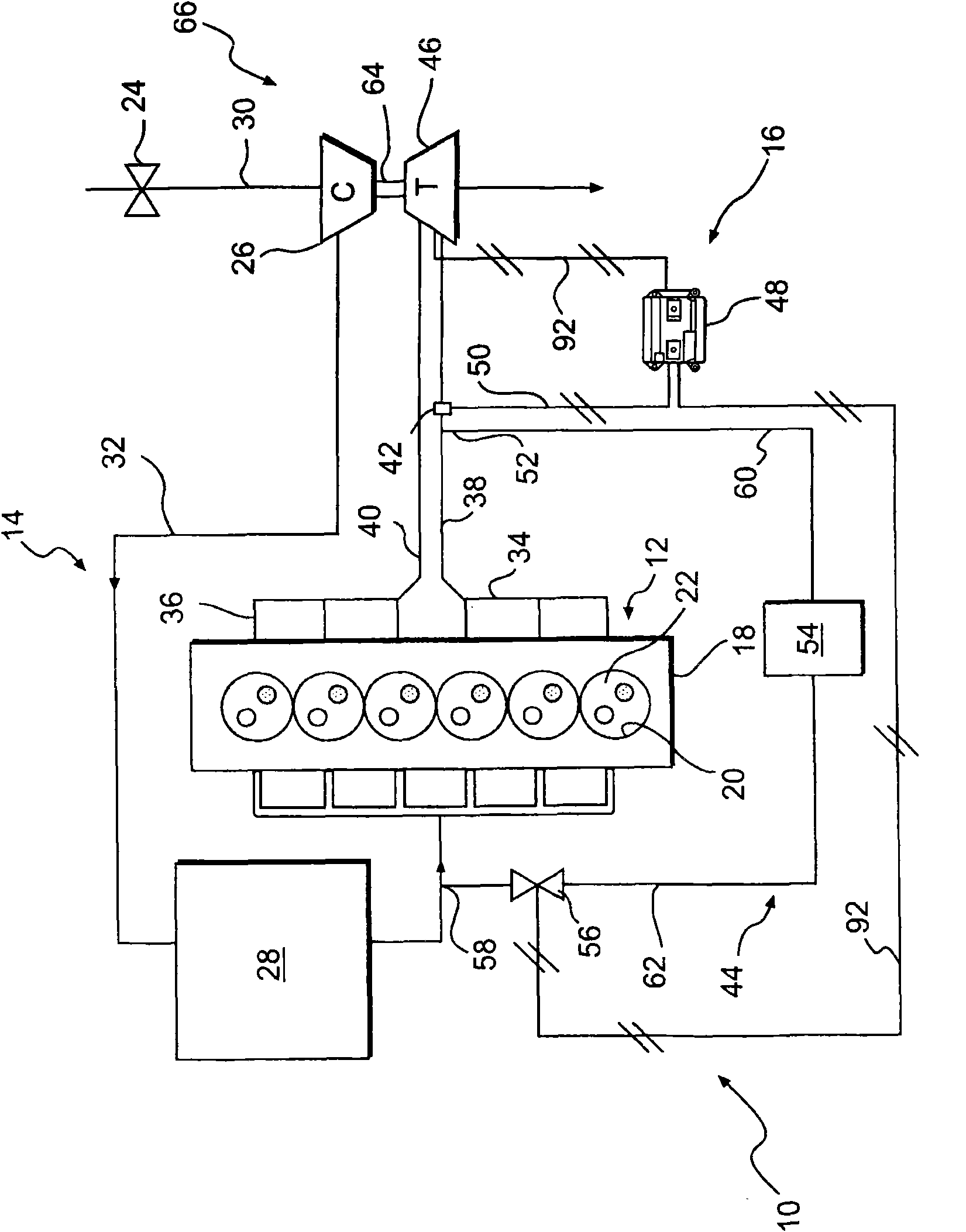
[0016] figure 1 A power system 10 is shown having a power source 12 , an intake system 14 , and an exhaust system 16 . For the purposes of the present invention, power source 12 is shown and described as a four-stroke diesel engine. However, those skilled in the art will appreciate that power source 12 may be any other type of internal combustion engine, such as a gasoline engine or a gaseous fuel powered engine. Power source 12 may include an engine block 18 defining a plurality of cylinders 20 . A piston (not shown) is slidably disposed in each cylinder 20 to reciprocate between a top dead center position and a bottom dead center position, and each cylinder 20 may be coupled with a cylinder head (not shown).

[0017] Cylinder 20 , piston and cylinder head may form combustion chamber 22 . In the illustrated embodiment, power source 12 includes six such combustion chambers 22 . However, it is contemplated that power source 12 may include a greater or lesser number of combu...


PUM


Abstract

A turbocharger (66) is provided having a turbine wheel (68) and a housing (70) configured to at least partially enclose the turbine wheel. The housing may have a first turbine volute (76) including afirst inlet (78) and a second turbine volute (80) having a second inlet (82). The first and second volutes may be configured to communicate a first and a second fluid flow with the turbine wheel. Thehousing may also have a wall member (84) axially separating the first and second turbine volutes. In addition, the housing may have a valve (86) configured to selectively allow fluid in the first inlet to communicate with fluid in the second inlet.

Description

technical field [0001] The present invention relates to a turbocharger, and more particularly to a turbocharger having a segmented housing with integral valves. Background technique [0002] Internal combustion engines, such as diesel engines, gasoline engines and gaseous fuel powered engines, are supplied with a mixture of air and fuel for subsequent combustion within the engine to produce a mechanical power output. To maximize the power produced by this combustion process, engines are typically equipped with a branched exhaust manifold in fluid communication with the turbocharged intake system. [0003] A branched exhaust system increases engine power by helping to preserve the energy of the exhaust pulse produced by the engine cylinders. Retaining the exhaust pulse energy produced by the engine cylinders increases the efficiency of the turbocharger, which enables more efficient use of fuel and ultimately greater engine power output. Additionally, a turbo induction syste...

Claims


Application Information

Patent Timeline
Patent Type & Authority Applications(China)
IPC IPC(8): F01D9/02F01D17/14F01D17/16F02B37/18F02C6/12
CPCF02B37/025F01N13/107F02C6/12F01D9/026F05D2220/40F05B2220/40F01D17/165Y02T10/144F01D17/145Y02T10/12
Inventor D·A·皮尔庞特P·W·赖斯多夫
Owner CATERPILLAR INC
Why Eureka
Try Eureka