Motor drive system and its control method

一种电机驱动系统、电机电流的技术,应用在电动机控制、电动发电机控制、交流电动机控制等方向,能够解决降低载波频率、成本上升、变化等问题,达到防止磁体温度上升、防止开关损失的增大的效果

Active Publication Date: 2010-03-31
DENSO CORP
View PDF5 Cites 17 Cited by
  • Summary
  • Abstract
  • Description
  • Claims
  • Application Information

AI Technical Summary

Problems solved by technology

In addition, in the PWM power conversion device of Patent Document 1, it is necessary to additionally arrange a series resonant circuit, so the cost increases due to an increase in the number of components.
[0012] In addition, in the current control device of the VVVF converter disclosed in Patent Document 2, the following feedback control is performed, but it is not disclosed that the magnitude of the AC component (ripple current) in each phase current is controlled to an appropriate level. It is to increase the carrier frequency when the deviation from the command value of each phase current is large, and to reduce the carrier frequency when the difference is small
[0013] On the other hand, in the power conversion device disclosed in Patent Document 4, the ripple current can be minimized even when the carrier frequency is changed by properly controlling the phase difference of the carrier signal between the two converters. Controlling the magnitude of the pulsating current to an appropriate level is not disclosed
In addition, the AC motor control device described in Patent Document 5 is a device for controlling a permanent magnet synchronous motor, but does not disclose changing the carrier frequency according to the ripple current.

Method used


Image

  • Motor drive system and its control method
  • Motor drive system and its control method
  • Motor drive system and its control method

Examples


Embodiment Construction

[0044] Hereinafter, embodiments of the present invention will be described in detail with reference to the drawings. Hereinafter, the same reference numerals are assigned to the same or corresponding parts in the drawings, and detailed description thereof will not be repeated in principle.

[0045] (Overall structure of the system)

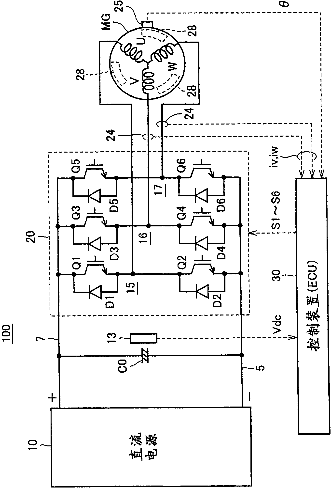
[0046] figure 1 It is an overall configuration diagram of the motor drive system according to the embodiment of the present invention.

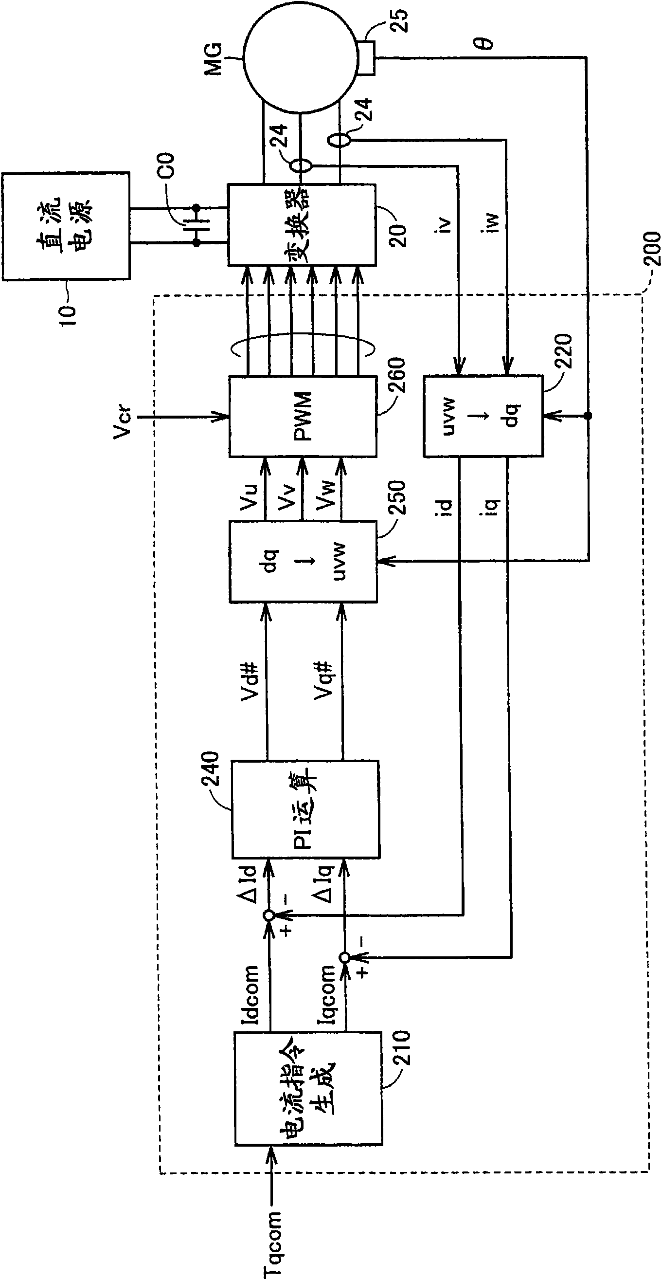
[0047] refer to figure 1 , The motor drive system 100 according to the embodiment of the present invention includes a DC power supply 10 , a voltage sensor 13 , a smoothing capacitor C0 , an inverter 20 , a control device 30 , and an AC motor MG as a load.

[0048] AC motor MG is, for example, a drive motor for generating torque for driving drive wheels of a hybrid vehicle or an electric vehicle. Alternatively, the AC motor MG may be configured to function as a generator driven by the engine, or may be config...


PUM


Abstract

A ripple detection unit (310) detects a ripple current width (Irp) of a motor current controlled according to PWM control. A ripple reference setting unit (320) sets a reference value (Irp#) of the ripple current width. A frequency adjusting unit (350) sets a control signal (Vfq) indicating a carrier frequency of the PWM control according to a ripple current width deviation. A carrier generation unit (360) generates a carrier (Vcr) of the frequency based on the control signal (Vfq). Thus, it is possible to realize feedback control of the carrier frequency for maintaining the ripple current width at an appropriate level.

Description

technical field [0001] The present invention relates to a motor drive system and its control method, in particular to a motor drive system with a pulse width modulation (PWM) controlled power converter and its control method. Background technique [0002] Among power converters that perform PWM control, there is known a configuration that variably controls the frequency of a carrier wave (carrier frequency) used in PWM control. For example, Japanese Unexamined Patent Publication No. 1-321868 (Patent Document 1) discloses a configuration in which a series resonant circuit is provided in parallel with a smoothing capacitor in a power conversion device that performs PWM control, and the carrier frequency of PWM control is variable. , so that the resonant frequency of the series resonant circuit coincides with the frequency of the pulsating component included in the DC current of the power conversion device accompanied by PWM control within a predetermined range. [0003] In ad...

Claims


Application Information

Patent Timeline
Patent Type & Authority Applications(China)
IPC IPC(8): H02P21/00H02P27/04H02P27/08H02P25/022
CPCH02M1/12H02M2001/0019H02P27/08H02P29/0066H02P29/0038H02M7/53875H02P27/085H02P27/10H02M1/0019
Inventor 山田坚滋
Owner DENSO CORP
Why Eureka
Try Eureka