Method and device for alignment and assembly of glass micro nanofluidic chip

A nanofluidic and glass-micro technology, which is applied in the field of glass micro-nanofluidic chip alignment and assembly, can solve the problems of high cost and achieve the effect of reducing manufacturing cost and difficulty, simple operation, precise and fast alignment

Inactive Publication Date: 2010-04-07
DALIAN UNIV OF TECH
View PDF1 Cites 16 Cited by
  • Summary
  • Abstract
  • Description
  • Claims
  • Application Information

AI Technical Summary

Problems solved by technology

Using a micro-assembly robot system to complete the alignm

Method used


Image

  • Method and device for alignment and assembly of glass micro nanofluidic chip
  • Method and device for alignment and assembly of glass micro nanofluidic chip
  • Method and device for alignment and assembly of glass micro nanofluidic chip

Examples


Embodiment 1

[0027] Embodiment 1: Three-dimensional micro mobile platform device

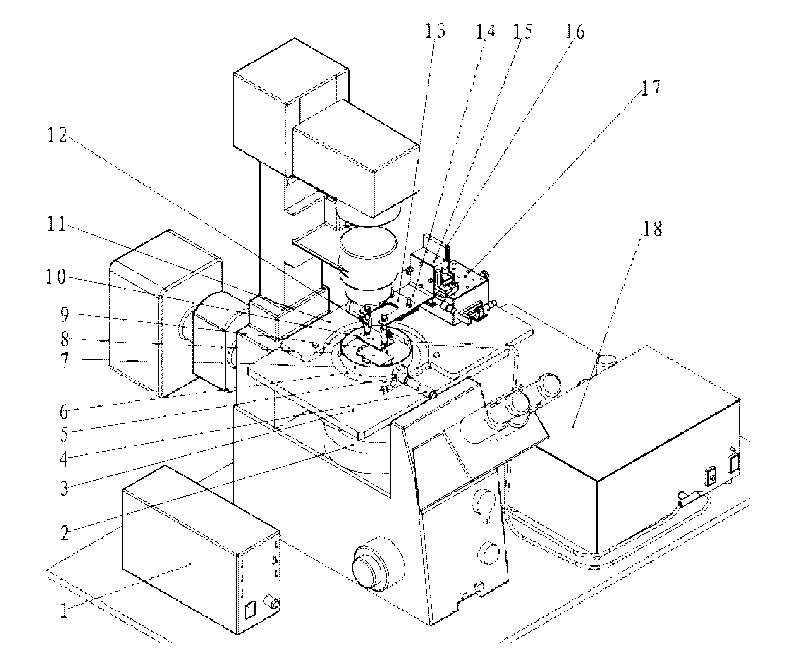
[0028] combined with figure 1 The configuration of the three-dimensional micro mobile station device according to the present invention will be described. The three-dimensional micro-moving device is mainly composed of a spiral measuring micrometer head 4, a spiral measuring micrometer head mounting seat 5, a cover plate 6, a chip container 7, a magnetic strip 9, a connecting plate 11, a vacuum chuck 12, a vacuum chuck mounting plate 13, and a right-angle plate 14 , a manual one-way micro-moving platform 15, a right-angle mounting plate 16, a manual two-way micro-moving platform 17 and the like. Install the spiral micrometer sub-head 4 on the spiral micrometer sub-head mounting base 5, then fix the installed spiral micrometer sub-head mounting base 5 together with the connecting plate 11 on the microscope stage 3, and put the cover plate 6 on the microscope In the circular groove corresponding to the stage...

Embodiment 2

[0029] Embodiment 2: vacuum adsorption device

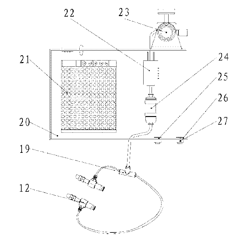
[0030] combined with figure 2 The structure of the vacuum adsorption apparatus concerning this invention is demonstrated. The vacuum adsorption device is mainly composed of a T-shaped connecting pipe 19, a box body 20, a DC power supply 21, a three-way solenoid valve 22, a vacuum air-conditioning valve 23, a vacuum filter 24, a power switch 25, a three-way solenoid valve switch 26, an indicator light 27, Vacuum pump 28 etc. are formed. Fix the DC power supply 21, the three-way electromagnetic valve 22, and the vacuum filter 24 on the bottom panel of the casing 20, and fix the vacuum pressure valve 23 on the rear panel of the casing 20 so that it is outside the casing 20, In order to check and adjust the vacuum pressure, a power switch 25, a three-way solenoid valve switch 26 and an indicator light 27 are fixed on the front panel of the box body 20 for easy operation by the operator.

Embodiment 3

[0031] Embodiment 3: the adsorption of vacuum adsorption device

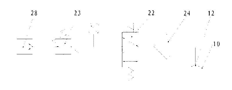
[0032] combined with image 3 The adsorption principle of the vacuum adsorption device according to the present invention will be described. Connect the vacuum pump 28, the vacuum air-conditioning valve 23 with the vacuum pressure gauge, the three-way solenoid valve 22, the vacuum filter 24, the T-shaped connecting pipe 19, and the vacuum chuck 12 in sequence with a flexible pipe. When the vacuum pump 28 is turned on, the three-way electromagnetic valve 22 is closed, and the air circuit with the vacuum chuck 12 is connected with the normal port of the three-way electromagnetic valve 22, and is connected to the atmosphere. When the three-way solenoid valve 22 is opened, the vacuum pump 28 is connected to the vacuum chuck 12 along the air path, and the vacuum chuck 12 can be used to suck the chip at this moment. After completing the operation, close the three-way electromagnetic valve 22, and now the vacuum chuc...


PUM


Abstract

The invention discloses a method and a device for the alignment and assembly of a glass micro nanofluidic chip and belongs to the field of microelement assembly. In the method for the alignment and assembly of the glass micro nanofluidic chip, a microscope is adopted to observe the alignment condition of the glass micro nanofluidic chip, and a method of a fixed substrate and a movable cover plate is adopted to realize the micro nanochannel alignment between the cover plate and the substrate. The device observes the alignment condition of the glass micro nanofluidic chip by the inverted high-power microscope and drives a vacuum sucker absorbing the cover plate to move by a three-dimensional micro motion table, thereby realizing the three-dimensional micro motion of the cover plate. The device consists of the three-dimensional micro motion table, the vacuum absorption device, the inverted microscope and a micro hot plate. The method and the device can reduce the manufacturing period of the chip, reduce the manufacturing cost and difficulty of the chip and meet the increasing complex inter-channel alignment requirements.

Description

technical field [0001] The invention relates to a method and device for aligning and assembling a glass micro-nanofluidic chip with microstructures on both the substrate and the cover, belonging to the field of micro-miniature device assembly, and relates to a method for aligning and assembling using vacuum adsorption and three-dimensional micro-movement. device. Background technique [0002] High-precision microstructures can be processed on glass materials, and the geometric structure and surface characteristics of the processed microstructures are not easy to change with changes in the environment, which is of great significance for micro-total analysis systems and microfluidic systems. The fabrication of glass micro-nanofluidic chips includes micro-nano channel forming, alignment assembly, pre-connection and bonding. Processing different microstructures on the substrate and the cover sheet can help to change the form of the chip structure, shorten the manufacturing cycl...

Claims


Application Information

Patent Timeline
IPC IPC(8): B81C1/00B81C3/00B82B3/00G01B11/00G01B5/00
Inventor 徐征王德佳刘冲温金开刘军山杜立群
Owner DALIAN UNIV OF TECH
Why Eureka
Try Eureka