An organic electroluminescent device
An electroluminescence display and luminescence technology, which is applied in the direction of electric solid-state devices, electrical components, semiconductor devices, etc., can solve the problems of increased cost, easy fusing of the slope area, and consumption, etc., to improve the product yield rate, the effect is obvious, The effect of reducing the probability of disconnection
- Summary
- Abstract
- Description
- Claims
- Application Information
AI Technical Summary
Problems solved by technology
Method used
Image
Examples
Embodiment 1
[0044] Embodiment 1 is an OLED display device, and its preparation method is as follows:
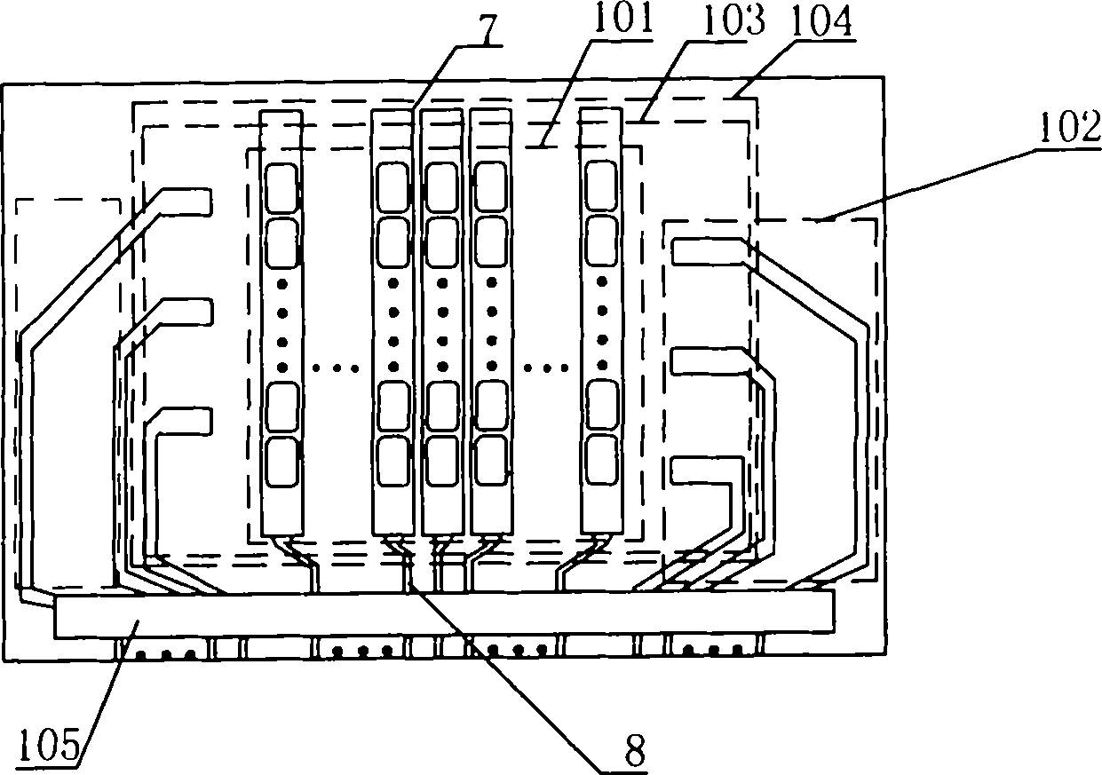
[0045] (1) Sputter the entire layer of ITO5 on the glass substrate 4 . Part of the ITO pattern after photolithography is used as the first electrode 7 and the first electrode lead 8 of the light emitting region 101 , and the other part is used as the second electrode lead of the second electrode lead region 102 .
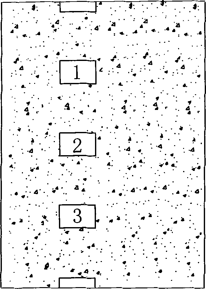
[0046] (2) Prepare an insulating layer and a spacer column (not shown) by photolithography, which is a necessary process for realizing RGB color, and different pixels are separated to realize a pixel array. The covering area of the insulating layer material is 104, and rectangular through holes 1a, 1b, 2a, 2b, 3a, 3b, etc. are formed between the insulating layer materials in the overlapping areas.
[0047] (3) The organic electroluminescence material is deposited by vacuum evaporation method to form the organic functional layer 14, including the hole injection layer 9, the ...
Embodiment 2
[0054] The difference between embodiment 2 and comparative example 1 is in steps (1) and (2):
[0055] (1) On the glass substrate 4, the whole layer of ITO5 and chromium 6 is sputtered. The pattern of chromium is etched first, and then the pattern of ITO is etched. Part of the photoetched ITO and chromium pattern is used as the first electrode and the first electrode lead of the light emitting region 101 , and the other part is used as the electrode lead of the second electrode lead region 102 .
[0056] (2) Prepare an insulating layer and isolation posts (not shown) by photolithography. Such as Figure 8 As shown, each lead wire of the second electrode overlaps with the second electrode through four rectangular through holes between the insulating layers.
Embodiment 3
[0058] The difference between embodiment 3 and comparative example 1 is in steps (1) and (2):
[0059] (1) Sputter ITO5 on the position of the light-emitting area on the glass substrate. Molybdenum, aluminum, and molybdenum materials are sequentially sputtered in the second electrode lead area to form a three-layer structure of molybdenum / aluminum / molybdenum. The ITO pattern of the light-emitting area 101 is firstly etched to serve as the first electrode and the first electrode lead; and then the second electrode lead area 102 is etched to form the molybdenum / aluminum / molybdenum pattern as the second electrode lead.
[0060] (2) Prepare an insulating layer and isolation posts (not shown) by photolithography. Such as Figure 9 As shown, each lead wire of the second electrode overlaps with the second electrode through two circular through holes between the insulating layers.
PUM
 Abstract
Description
Claims
Application Information
 - R&D
- Intellectual Property
- Life Sciences
- Materials
- Tech Scout
- Unparalleled Data Quality
- Higher Quality Content
- 60% Fewer Hallucinations
Browse by: Latest US Patents, China's latest patents, Technical Efficacy Thesaurus, Application Domain, Technology Topic, Popular Technical Reports.
© 2025 PatSnap. All rights reserved.Legal|Privacy policy|Modern Slavery Act Transparency Statement|Sitemap|About US| Contact US: help@patsnap.com


