Multi-locomotive fixing and rolling test platform

A technology for rolling test benches and locomotives, which is applied in railway vehicle testing and other directions, and can solve the problems of locomotive dynamic instability adjustment accuracy, time-consuming, and many mechanical parts, so as to shorten the preparation time for mechanical adjustments, reduce the horizontal footprint, The effect of simple mechanical structure

Inactive Publication Date: 2010-04-14
SOUTHWEST JIAOTONG UNIV
View PDF0 Cites 13 Cited by
  • Summary
  • Abstract
  • Description
  • Claims
  • Application Information

AI Technical Summary

Problems solved by technology

The locomotive is tested on the test bench, and its speed is only reflected by the locomotive wheel speed, and the locomotive body does not move. Therefore, the equivalent moment of inertia reflected in the traction motor rotation dynamics equation is reduced to about 1 / 20 of the line test. Influenced by the locomotive closed-loop control system designed according to the line operating conditions, the speed may be unstable in the fixed rolling test
The dynamic instability of this locomotive is the main obstacle to achieve the accuracy of electrical synchronous regulation
[0016] 3) The stationary rolling test bench simulates the test process of two infinitely long straight rails through multiple independent track wheelsets. Many factors will cause the speed of each track wheel set to be different, making the locomotive mistaken for a certain track wheel set. Some wheel sets stop torque output due to idling, and then resume output to them, making the locomotive run unstable; especially when the locomotive starts, the output torque will stop frequently, making the locomotive unable to start normally
In order to ensure the synchronization of the rotation angles of each track wheel pair, the existing test benches mostly use bevel gears to connect all the track wheel shafts, which makes it have many mechanical parts, long intermediate connecting shafts, complicated test equipment, and reduced reliability.
At the same time, in order to align locomotives with different wheelbases, numerous mechanical connecting parts also make the mechanical adjustment workload heavy, and the long axis is still a factor that causes additional vibration and unsafety
[0017] In view of the problem of the mechanical synchronization scheme, some fixed rolling test benches in China adopt the scheme of adjusting the exciting current of each DC motor to make the rotational speed of the track wheel pair tend to be consistent, such as the 1981 "speed regulation of the dynamometer device of the diesel locomotive test bench". System", this kind of scheme needs to add an additional measurement and control closed-loop system. At the same time, because all the traction motors of the locomotive are connected in parallel in the "vehicle control" mode, and 2 to 3 motors are connected in parallel in the frame control, driven by the public power supply, these There is a coupling relationship between the speed and torque of the motor caused by the shared power supply. When the test bench adjusts the speed of a track wheel set, the speed of other driving wheels with coupling relationship will also change, resulting in cross interference
Moreover, the mechanical characteristics of the resistance braking DC motor are very soft, and the adjustment speed is slow. In practical applications, this solution needs to be adjusted repeatedly for a specific locomotive at least, which is very inconvenient to use. The problem of speed instability, it is difficult to achieve satisfactory synchronous rotation
[0018] 4) In view of the fact that the single locomotive test bench requires a large power accompanying electrical system, the investment is high
Therefore, the requirements for the test plant are high, the test operation is complicated, and due to the limitation of the site, it is difficult to build a fixed rolling test bench in the existing maintenance plant and section
[0020] In short, the existing multi-locomotive test bench scheme either adopts bevel gear synchronization, or relies on the excitation adjustment of the DC motor to achieve electrical synchronization; the former requires a lot of work to adjust to the different wheelbases of the locomotives before the test, while the latter Then in the test process, because the adjustment effect is always unsatisfactory, it takes a lot of time

Method used


Image

  • Multi-locomotive fixing and rolling test platform
  • Multi-locomotive fixing and rolling test platform
  • Multi-locomotive fixing and rolling test platform

Examples


Embodiment 1

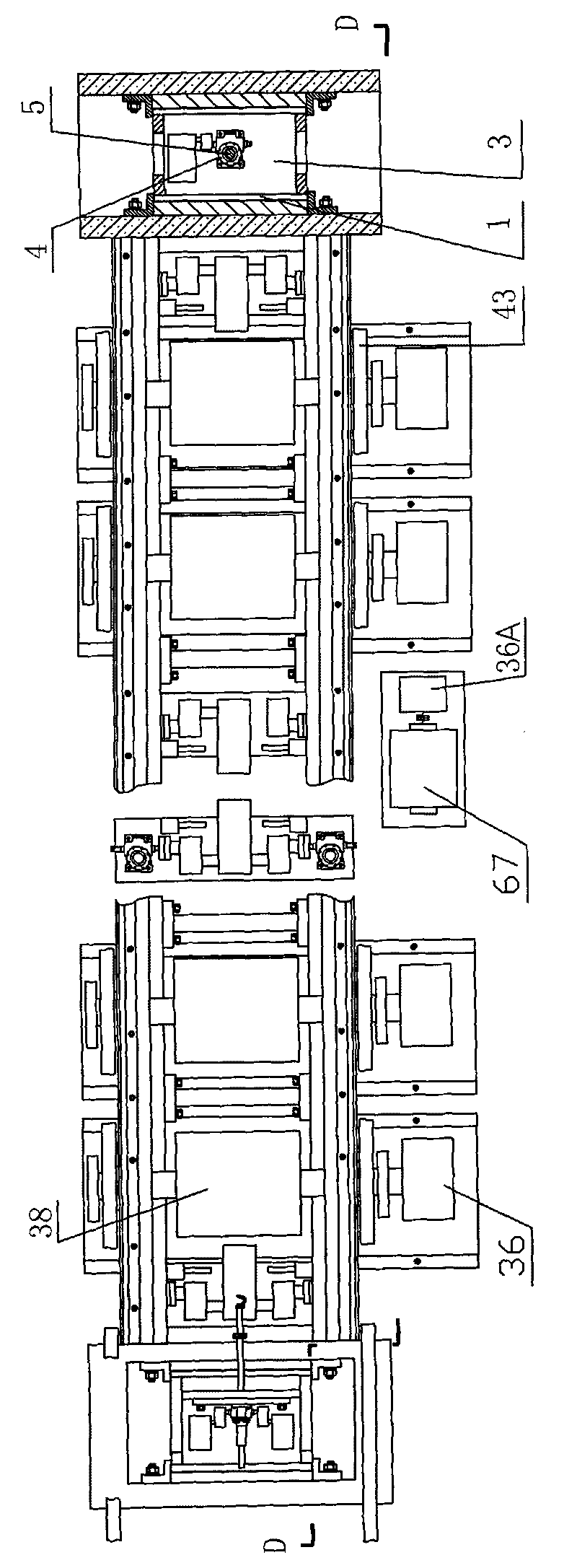
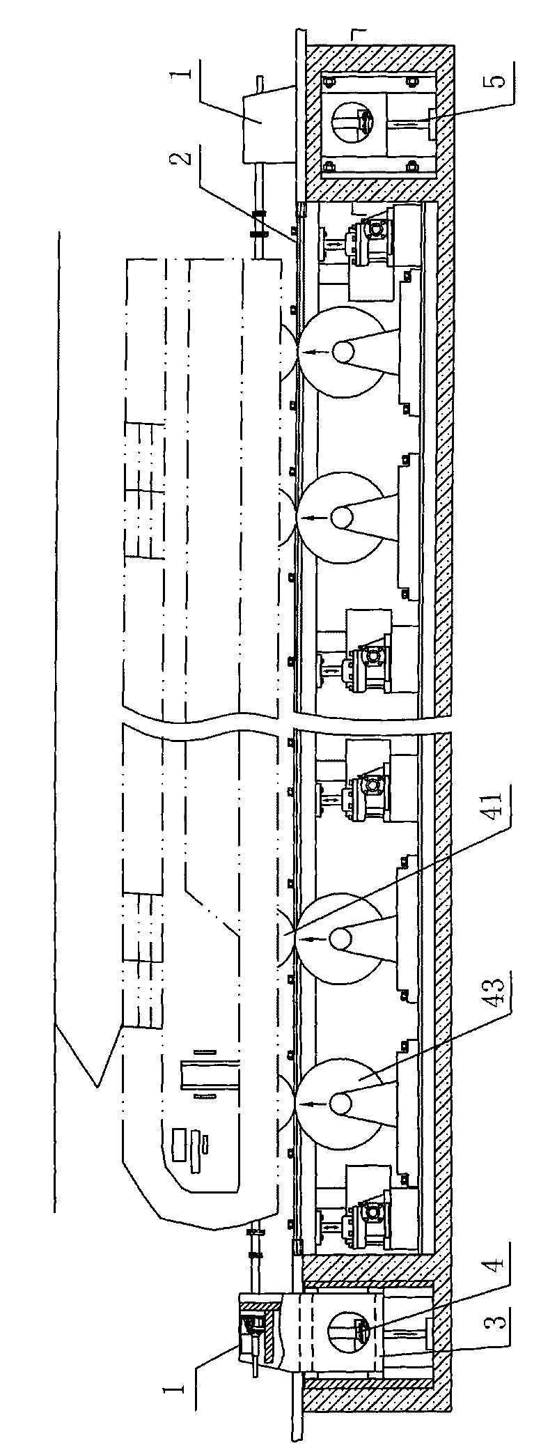
[0056] figure 1 , 3 , 4 and 7 show that a specific embodiment of the present invention is: a multi-locomotive fixed rolling test bench, including two test bench positions A, B, wherein each test bench position A or B includes a pair of A test unit group consisting of a reaction force frame 1, an upper axle 2 and test units with the same number of wheel pairs 41 as a single locomotive.

[0057] The composition of all test units is that the shaft of the track wheel pair 43 supporting the locomotive wheel pair 41 is connected to the shaft of the wound asynchronous motor 36, and the diameter / length ratio of the wound asynchronous motor is greater than 1.

[0058] Figure 7 It is shown that the stator windings of each wound asynchronous motor 36 in each test unit group are connected in parallel to the stator three-phase busbar 53 of the asynchronous motor, and are connected to the power grid through a three-phase switch one 63; the rotor windings are connected in parallel to the ...
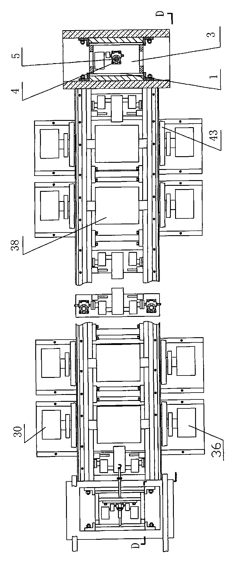
Embodiment 2

[0065] figure 2 , 3, 5, and 8 show that this example is basically the same as Embodiment 1, and the difference is only that the test bench positions are A, B, and C, among which there is a test bench position A as the main test bench position, and the main test bench position The shaft of the track wheel pair 43 in the test unit of position A is also connected with the shaft of the synchronous motor 30, the diameter / length ratio of the synchronous motor 30 is greater than 1, and the synchronous motors 30 of each test unit of the main test bench position are electrically connected The specific method is: the stator winding of the synchronous motor 30 is connected in parallel to the three-phase busbar 61 of the stator of the synchronous motor, and the three-phase busbar 61 of the stator of the synchronous motor is connected to three star-connected resistors 65 (i.e. three resistors) by three-phase switch seven 64 65 is not connected with the other end of the three-phase switch...


PUM


Abstract

The invention relates to a multi-locomotive fixing and rolling test platform which comprises two or three test platforms. Each test platform comprises a pair of counter-force frames (1), an upper axle (2) and test unit groups, wherein the test unit groups comprise test units having same number with single locomotive wheel pairs (41). All the test units adopt the structure that shafts of a track wheel pair (43) for supporting the locomotive wheel pairs (41) are connected with shafts of winding asynchronous motors (36), and the diameter/length ratio of the winding asynchronous motors is larger than 1; stator windings of all the winding asynchronous motors (36) of each test unit group are connected with a power grid by a three-phase switch I (63) of a stator three-phase bus bar (53) of each asynchronous motor, and rotor windings are connected in parallel to a rotor three-phase bus bar (49) of each asynchronous motor; and the rotor three-phase bus bars of the asynchronous motors of all the test unit groups are connected by a breaker (62). The test platform carries out a mutual accompanying test by multiple locomotives and has reliable synchronization and convenient test and can form the mutual feedback of energy, reduce the capacity of a power supply and save energy sources and cost.

Description

technical field [0001] The invention relates to a stationary rolling test bench for railway diesel locomotives, electric locomotives, main line trains and subway trains. Background technique [0002] The function of railway electric locomotives or diesel locomotives is to traction trains, and the main working conditions are traction and braking; the main working conditions of trunk line trains and subway trains are also traction and braking: [0003] 1. Traction working condition: After the electric energy obtained by the electric locomotive from the power grid is converted into an appropriate voltage (including frequency) by the converter, it is converted into mechanical kinetic energy by the traction motor, which can output the energy controlled by the driver at different speeds. The traction force makes the train accelerate or run at a steady speed; for a diesel locomotive, the internal combustion engine first converts the thermal energy of the fuel into mechanical energy...

Claims


Application Information

Patent Timeline
Patent Type & Authority Applications(China)
IPC IPC(8): G01M17/08
Inventor 周文祥卢瑞彪孙效杰邹晓霞郭成磊苏焘沈玉飞黄辰彭艳郭杨
Owner SOUTHWEST JIAOTONG UNIV
Why Eureka
Try Eureka