Lightwave stove
A light-wave furnace and furnace body technology, applied in the field of light-wave furnace, can solve the problems of high efficiency, achieve the effects of enhancing immunity, accelerating metabolism, and activating human tissue cells
- Summary
- Abstract
- Description
- Claims
- Application Information
AI Technical Summary
Problems solved by technology
Method used
Image
Examples
Embodiment 1
[0024] Schematic diagram of the structure of the stove-type light-emitting diode light-wave oven, see figure 1 The light-emitting diodes 1 are fixed on the heat-dissipating and light-reflecting brackets 2 that play the role of heat dissipation and light-concentrating reflection. The radiation wavelength of the light-emitting diodes is 0.4 μm to 200 μm (the preferred radiation wavelength is 1 μm to 30 μm), and the light-emitting diodes are circularly distributed. The panel 3 not only supports the cooking utensils, transmits heat, but also transmits the light 4 . The housing 5 has a cooling fan 6 and a power and temperature controller 7 . The light-emitting diode light-wave oven has the feature of not picking pots, and any pans made of high-temperature resistant materials are suitable, such as ceramic pots, casserole pots, stainless steel pots, iron pots, aluminum pots, glass pots, etc., making up for the fact that induction cookers can only use iron pots Tool defects. Usually ...
Embodiment 2
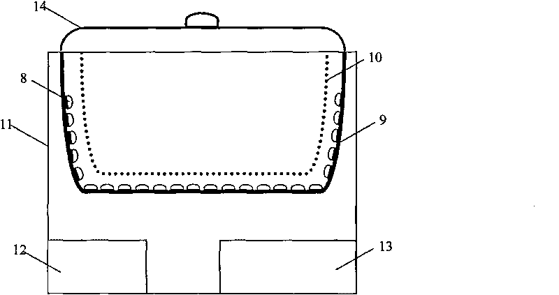
[0026] The schematic diagram of the structure of the pot-type light-emitting diode light-wave furnace is shown in figure 2 . Infrared light-emitting diodes 8 are fixed on heat dissipation and reflective brackets 9 for heat dissipation and light-concentrating reflection. The radiation wavelength of the light-emitting diodes is 0.4 μm to 200 μm (preferred radiation wavelength is 1 μm to 30 μm), and the light-emitting diodes are distributed in a parabolic shape. The glass pot 10 not only has the functions of holding food and transferring heat, but also has the function of penetrating infrared rays. In the shell 11, a cooling fan 12 and a power and temperature controller 13 are arranged. The light-wave oven can realize various cooking methods such as steaming, roasting, stewing, etc. It can bake grilled food that is charred on the outside and tender on the inside, and can realize oil-free and low-fat cooking. Nutrients of the food are not lost and many other advantages.
[0027...
Embodiment 3
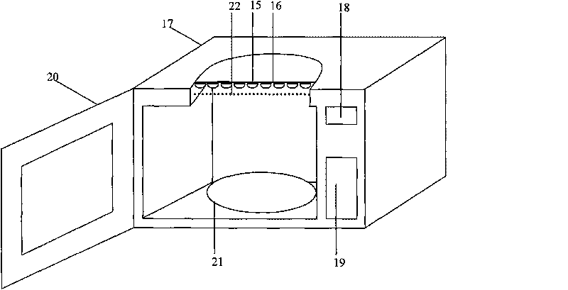
[0029] The structural diagram of the box-type light-emitting diode light-wave furnace is shown in image 3 The infrared light-emitting diodes 15 are fixed on the heat dissipation and reflective support 15 that play the role of heat dissipation and light-concentrating reflection. The radiation wavelength of the light-emitting diodes is 0.4 μm to 200 μm (preferred radiation wavelength is 1 μm to 30 μm), and the light-emitting diodes are distributed in a square shape. The panel 22 transmits infrared rays, and the housing 17 has cooling fans, power and temperature controllers, as well as control buttons 18 and display components 19 . Door 20 and tray 21 are the same as microwave ovens. When the infrared light-emitting diode is working, it radiates red light and infrared rays. After the red light and infrared rays are transmitted through the panel, the food is heated, and the air in the furnace is also heated, and the hot air is blown to the food to be heated by the forced convecti...
PUM
 Abstract
Description
Claims
Application Information
 - R&D
- Intellectual Property
- Life Sciences
- Materials
- Tech Scout
- Unparalleled Data Quality
- Higher Quality Content
- 60% Fewer Hallucinations
Browse by: Latest US Patents, China's latest patents, Technical Efficacy Thesaurus, Application Domain, Technology Topic, Popular Technical Reports.
© 2025 PatSnap. All rights reserved.Legal|Privacy policy|Modern Slavery Act Transparency Statement|Sitemap|About US| Contact US: help@patsnap.com


