Gas dehumidifying device with controllable supersonic speed of shock wave

A supersonic and shock wave technology, applied in gas fuel, petroleum industry, dispersed particle separation, etc., can solve problems such as unpublished test results, and achieve the effect of avoiding boundary layer separation, good effect and smooth flow

Active Publication Date: 2010-05-05
XI AN JIAOTONG UNIV
View PDF0 Cites 25 Cited by
  • Summary
  • Abstract
  • Description
  • Claims
  • Application Information

AI Technical Summary

Problems solved by technology

[0005] According to published information, China University of Petroleum (East China), Beijing University of Technology, and Jianghan Petroleum Machinery Research Institute have completed preliminary numerical simulations and field tests, but all of them have adopted the delta-wing induced swirl scheme ; Dalian Universi

Method used


Image

  • Gas dehumidifying device with controllable supersonic speed of shock wave
  • Gas dehumidifying device with controllable supersonic speed of shock wave
  • Gas dehumidifying device with controllable supersonic speed of shock wave

Examples


Embodiment Construction

[0013] The structural principle and working principle of the present invention will be further described in detail below in conjunction with the accompanying drawings.

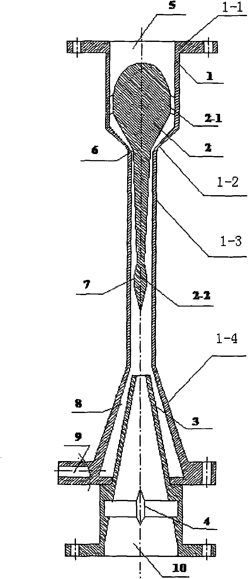
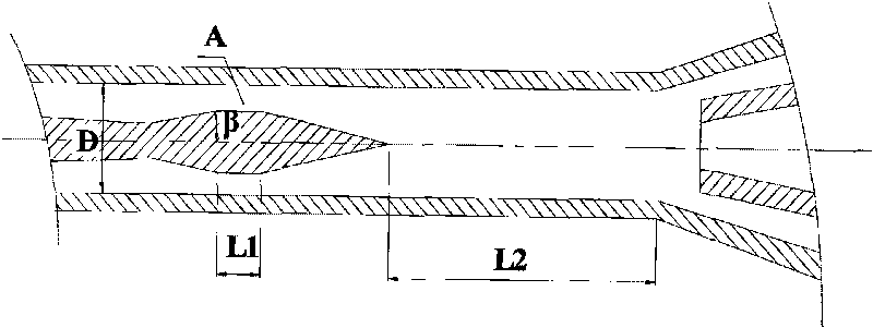
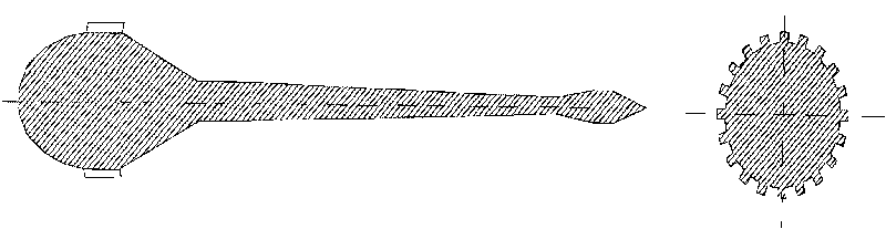
[0014] see figure 1 . -1 is provided with a central worm 2 with guide vanes 2-1, an annular channel is formed between the central worm 2 with guide vanes 2-1 and the pipeline 1, and the flow area of ​​the annular channel shrinks first along the flow direction At throat 6, that is, the junction of tapered section 1-2 and straight section 1-3, it reaches the minimum, and its value is A t , after passing through the throat 6, it enters the equal straight section 1-3 and then expands, and finally shrinks again in the shock wave compression zone 7 at the end of the central worm 2, where the minimum flow area is A, and in the expansion section 1 of the shell 1 -4 is provided with a liquid collector 3, a liquid collecting chamber 8 is formed between the liquid collecting device 3 and the shell, and a liquid dischar...


PUM


Abstract

The invention relates to a gas dehumidifying device with a controllable supersonic speed of a shock wave. The air current generates strong rotation when passing a guide vane grid, swells and accelerates to a supersonic speed through a contractile annular channel; the tail end of a central worm is a compression region of the shock wave, and in the compression region, the air current of the supersonic speed decelerates to a subsonic speed through the compression of an oblique shock wave and a normal shock wave; liquid drops continuously grow in the subsonic speed section, move to the outer side of a pipeline under the action of the centrifugal force, and finally enter a liquid-collecting chamber to be discharged by a liquid outlet; while the dry gas enters an exhaust chamber and is discharged by an air outlet. In the invention, the compression region of the shock wave is designed, and the growth region of liquid drops is divided into the supersonic speed region and the subsonic speed region, and the total length of the pipeline is effectively shortened by optimizing the length of the two parts, thereby the loss of frictional resistance caused by the interaction of the air current and the pipeline is reduced; the shape of shock wave in the compression region of the shock wave are designed as the oblique shock wave and the normal shock wave, thereby the strength of a single shock wave is weakened, the loss of the resistance of the shock wave is reduced, and the separation of boundary layers induced by the strong shock wave is avoided.

Description

technical field [0001] The invention relates to the technical field of gas dehumidification, in particular to a shock wave controllable supersonic gas dehumidification device for removing water and heavy hydrocarbons in the field of natural gas processing. Background technique [0002] Natural gas is an efficient and clean energy source. However, the extracted natural gas contains many impurities. In order to meet the requirements of transportation and use, water vapor and heavy hydrocarbons must be removed. At present, the dehydration technologies used in domestic natural gas gathering and transportation systems mainly include: triethylene glycol dehydration system in Changqing Oilfield, J-T valve low-temperature separation system in Southwest Oilfield, turboexpander dehydration system in Daqing Oilfield, molecular sieve dehydration and low-temperature separation in Tarim Gasfield These technical equipment are not only complex in structure but also high in operating costs. ...

Claims


Application Information

Patent Timeline
IPC IPC(8): B01D53/26C10L3/10
Inventor 白博峰常春
Owner XI AN JIAOTONG UNIV
Why Eureka
Try Eureka