Oil-water composite cabin for ship

A technology for marine oil and liquid tanks, applied in the field of ships, can solve the problems of aggravated ship swaying motion and affect the seaworthiness performance, and achieve the effects of reducing pollution, facilitating daily maintenance, and suppressing sloshing.

Inactive Publication Date: 2010-05-05
NAVAL UNIV OF ENG PLA
View PDF0 Cites 10 Cited by
  • Summary
  • Abstract
  • Description
  • Claims
  • Application Information

AI Technical Summary

Problems solved by technology

When they are navigating at sea, the wind, waves and currents on the sea will inevitably cause the ship to sway. Due to the existence of the free liquid surface in the cabin, the sloshing movement of the li

Method used


Image

  • Oil-water composite cabin for ship
  • Oil-water composite cabin for ship
  • Oil-water composite cabin for ship

Examples


Embodiment 1

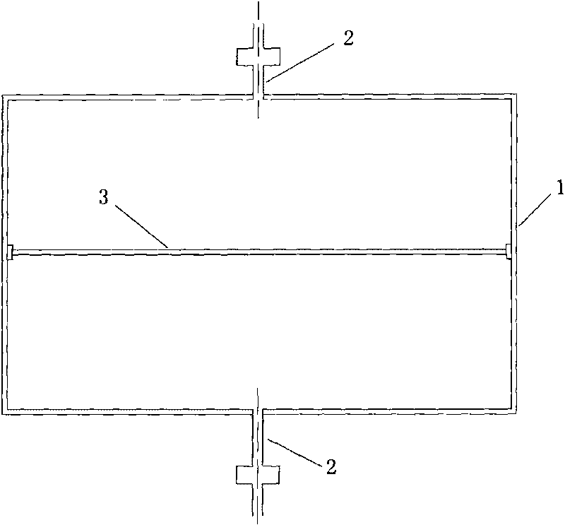
[0029] Embodiment 1: see figure 1 , The marine oil-water composite tank described in this embodiment includes a liquid tank 1, an infusion pipeline 2, a rigid partition 3, slide rails, a pressurization system and a push-pull system. Wherein, the liquid tank 1 is a cavity with a constant cross-section, the cross-section remains unchanged along the vertical direction, and slide rails are arranged on the vertical bulkhead. The rigid partition 3 is horizontally arranged in the liquid tank 1, cooperates watertightly with the bulkhead of the liquid tank 1, divides the liquid tank into two along the vertical direction of the liquid tank, the upper side is the fuel tank, and the lower side is the ballast water tank or Slop tank. The two ends of the rigid partition 3 cooperate with the slide rails provided on the bulkhead, and can move along the slide rails. The infusion pipeline 2 communicates with the compartments on both sides of the rigid partition 3 respectively. The pressuriza...

Embodiment 2

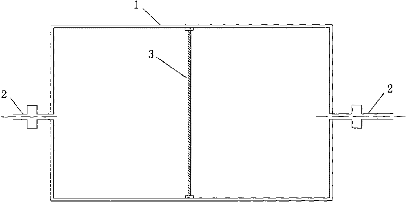
[0033] Example 2: see figure 2 , this embodiment is basically the same as Embodiment 1, except that the section of the liquid tank 1 along the horizontal direction remains unchanged, and slide rails are provided on the horizontal bulkhead. The rigid partition 3 is vertically arranged in the liquid tank 1, and cooperates watertightly with the bulkhead of the liquid tank 1, and divides the liquid tank into two along the horizontal direction of the liquid tank, one side is the fuel tank, and the other side is the ballast water tank or sewage tank.

Embodiment 3

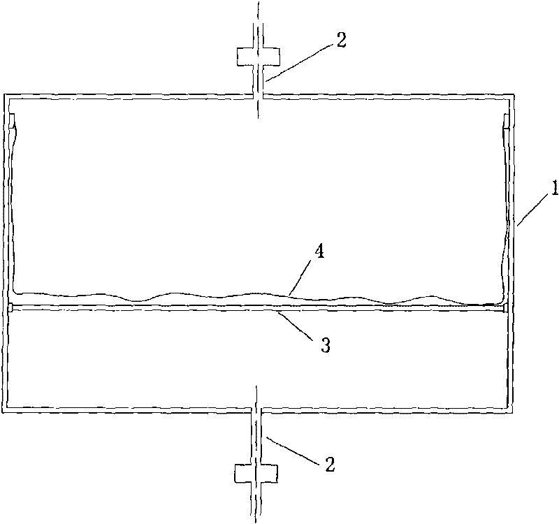
[0034] Embodiment 3: see image 3 , The marine oil-water composite tank described in this embodiment includes a liquid tank 1, an infusion pipeline 2, a rigid partition 3, an elastic bladder 4, slide rails, a pressurization system and a push-pull system. Wherein, the liquid tank 1 is a cavity with a constant cross-section, the cross-section remains unchanged along the vertical direction, and slide rails are arranged on the vertical bulkhead. The rigid partition 3 is horizontally arranged in the liquid tank 1, and divides the liquid tank into two along the vertical direction of the liquid tank. The upper side is a fuel tank, and the lower side is a ballast water tank or sewage tank. The two ends of the rigid partition 3 cooperate with the slide rails provided on the bulkhead, and can move along the slide rails. The infusion pipeline 2 communicates with the compartments on both sides of the rigid partition 3 respectively. The elastic bag 4 has high elasticity, corrosion resist...


PUM


Abstract

The invention relates to an oil-water composite cabin for a ship, comprising a liquid cabin and perfusion pipelines. A separation unit is arranged in the middle of the liquid cabin, is in watertight match with the cabin wall of the liquid cabin and separates the liquid cabin into two parts; and the perfusion pipelines are respectively arranged in and communicated with the liquid cabins at both sides of the separation unit which moves towards both sides or stretches or withdraws along with the volume variance of liquid at both sides. The oil-water composite cabin for a ship realizes the composite use of any functional liquid cabin on the ship, integrates economic benefits and environment-friendly benefits, has simple structure, compact arrangement and convenient production, processing and daily maintenance and can be widely applied to various ships and ocean structural objects with liquid cabins.

Description

technical field [0001] The invention relates to the field of ships, in particular to an oil-water composite tank for ships. Background technique [0002] During the navigation of a ship, a large amount of fuel oil, lubricating oil, sewage and fresh water are consumed. Different routes and navigation areas will lead to changes in the navigation status. In order to adjust the navigation status of the ship, a large amount of ballast water is required. Therefore, in order to meet the water and oil problems on board, a large number of liquid tanks are generally provided. In order to achieve floating and sinking, submarines also need to be equipped with large-volume ballast water tanks; on some special ships, in order to meet the needs of special tasks, their navigation status changes frequently and rapidly. In addition to torque, it is also necessary to use changes in ballast water to adjust the navigation state. [0003] Conventional surface ships are often equipped with speci...

Claims


Application Information

Patent Timeline
IPC IPC(8): B63B11/00
Inventor 董文才欧勇鹏毕毅姚朝帮许勇
Owner NAVAL UNIV OF ENG PLA
Why Eureka
Try Eureka