
System for pre-testing and diagnosing electro magnetic interference of electronic equipment and method thereof

A technology of electronic equipment and electromagnetic radiation, which is applied in the field of electronic equipment electromagnetic radiation interference pre-test diagnosis system, can solve the problems of unable to eliminate white noise, loss of equipment radiation signal, submerging the radiation signal of the equipment under test, etc., and achieve the degree of automation and portability High, enhanced complementarity and synergy, conducive to expansion and improvement

Active Publication Date: 2010-05-05
CHINA SHIP DEV & DESIGN CENT
View PDF0 Cites 38 Cited by
  • Summary
  • Abstract
  • Description
  • Claims
  • Application Information

AI Technical Summary

Problems solved by technology

[0004] Although the above noise removal method is simple and convenient, it has three obvious defects: (1) white noise cannot be removed, and even the amplitude of white noise will increase, submerging the radiation signal of the device under test; (2) environmental noise and device radiation in different time periods The signal will change suddenly, and it is impossible to offset the environmental noise and reproduce the radiation signal of the equipment by subtraction; (3) when the frequency of the environmental noise overlaps with the equipment under test and submerges the signal of the equipment under test, the difference method will cause the equipment to radiate signal loss

Method used

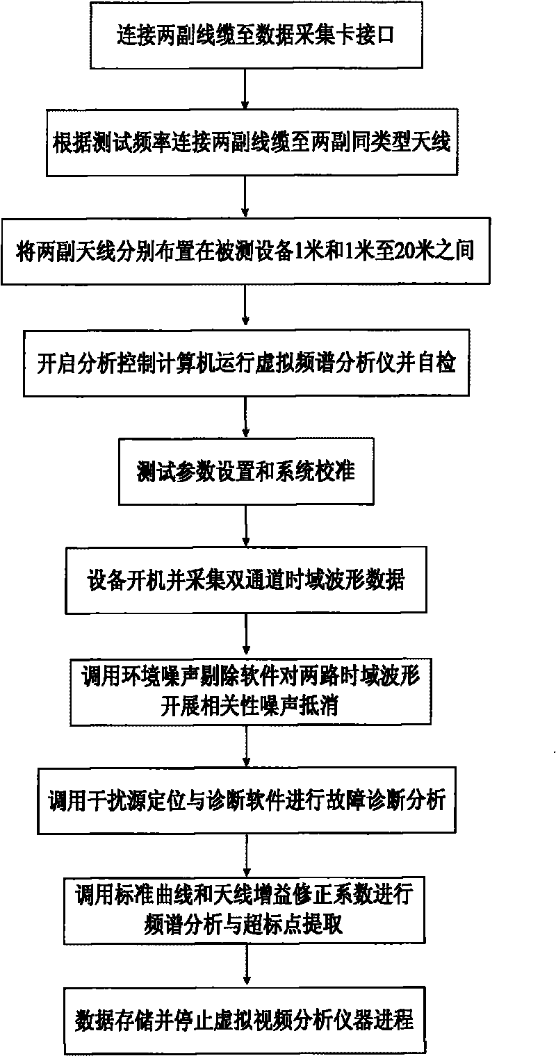

Image

  • System for pre-testing and diagnosing electro magnetic interference of electronic equipment and method thereof
  • System for pre-testing and diagnosing electro magnetic interference of electronic equipment and method thereof
  • System for pre-testing and diagnosing electro magnetic interference of electronic equipment and method thereof

Examples


Embodiment Construction

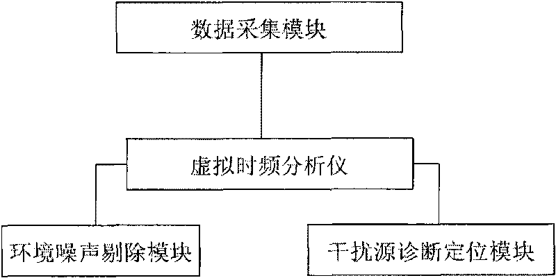
[0035] figure 1 It is a structural schematic diagram of an embodiment of the present invention, an electronic equipment electromagnetic radiation pre-test diagnostic system, including a data acquisition module, an interference source diagnosis and positioning module, an environmental noise elimination module and a virtual time-frequency analyzer; the data acquisition module, the interference source The diagnostic positioning module and the environmental noise elimination module are respectively connected with the virtual time-frequency analyzer, and the virtual time-frequency analyzer realizes the driving of the data acquisition module, the calling of the interference source diagnosis and positioning module and the environmental noise elimination module, and the monitoring of the time domain waveform and frequency spectrum show. Among them, the interference source diagnosis and positioning module, the environmental noise elimination module and the virtual time-frequency analyz...


PUM


Abstract

The invention discloses a system for pre-testing and diagnosing the electro magnetic interference of electronic equipment, which is characterized by comprising a data collecting module, an interference source diagnosing and locating module, an environmental noise eliminating module and a visual time-frequency analyzer, wherein the data collecting module, the interference source diagnosing and locating module and the environmental noise eliminating module are respectively connected with the visual time-frequency analyzer, and the visual time-frequency analyzer achieves the drive of the data collecting module, the call of the interference source diagnosing and locating module and the environmental noise eliminating module and the monitoring and displaying of time-domain waveforms and frequency spectrums. The invention also discloses a method for pre-testing and diagnosing the electro magnetic interference of electronic equipment, which utilizes a LabView visual instrument platform and Matlab programming environmental developing software to pre-test and diagnose signals. The invention can pre-test and diagnose the electro magnetic interference of electronic equipment at common test fields, and has high automation and carrying degree and simple usage and reduces cost.

Description

technical field [0001] The invention belongs to the technical field of electromagnetic compatibility testing, and in particular relates to a pre-testing and diagnosing system for electromagnetic radiation interference of electronic equipment in a non-standard environment. Background technique [0002] Electronic equipment must pass the electric field radiation interference standard compliance test and certification of the designated agency before leaving the factory. The relevant standards in my country have put forward clear requirements for the electronic equipment electric field radiation interference test site and test methods. The test equipment is placed in a shielded dark room at the same time to avoid the influence of environmental noise on the measurement, so as to effectively obtain the electromagnetic compatibility data of the tested equipment. However, the cost of standard test sites such as shielded darkrooms and special instruments is quite expensive, so that mo...

Claims


Application Information

Patent Timeline
IPC IPC(8): G01R23/16G01R29/08
Inventor 吴楠易学勤郑生全张嘉聂明新黄松高
Owner CHINA SHIP DEV & DESIGN CENT
Learn More