Supercharge Your Innovation With Domain-Expert AI Agents!

Gas nozzle with double gas source

A gas nozzle and dual gas source technology, which is applied to gas fuel burners, burners, combustion methods, etc., can solve the problems of difficult manufacturing and high noise, and achieve the effects of reducing manufacturing accuracy, eliminating noise, and reducing production costs.

Inactive Publication Date: 2010-05-12
PROCOM ELECTRIC APPLIANCES SHANGHAI
View PDF0 Cites 2 Cited by
  • Summary
  • Abstract
  • Description
  • Claims
  • Application Information

AI Technical Summary

Problems solved by technology

[0003] The purpose of the present invention is to design a movable dual-air source nozzle to overcome the noise and reduce the difficulty of manufacture and assembly in view of the problems of large noise and difficult manufacture in the existing fixed-structure dual-air source nozzle

Method used


Image

  • Gas nozzle with double gas source
  • Gas nozzle with double gas source
  • Gas nozzle with double gas source

Examples


Embodiment 1

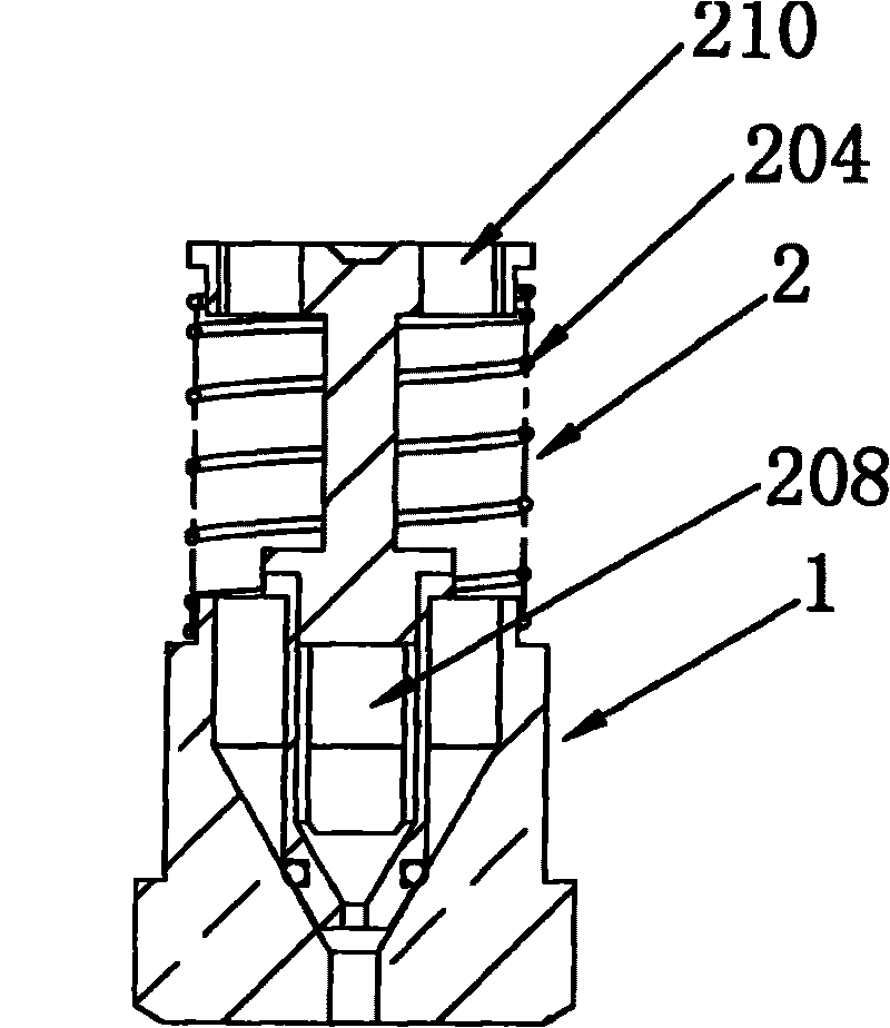
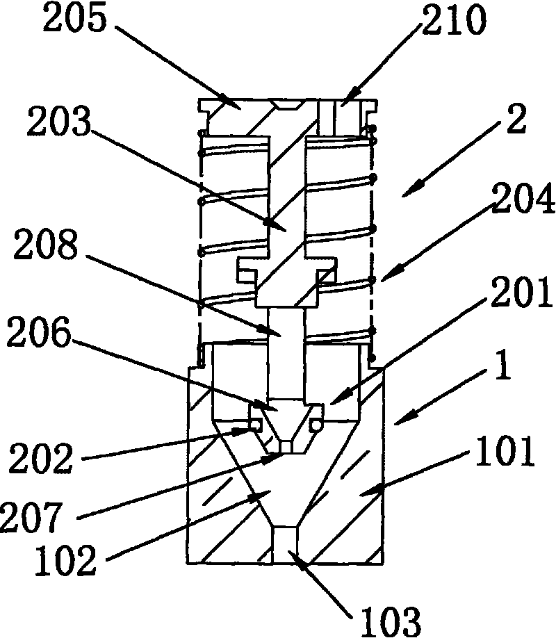
[0021] Such as figure 1 , 2 shown.

[0022] A dual gas source gas nozzle, comprising an outer nozzle 1 and an inner nozzle 2, the nozzle body 101 of the outer nozzle 1 is provided with an air cavity 102 and an injection hole 103 communicating with the air cavity 102, and the diameter of the injection hole 103 depends on The flow rate requirements of a specific type of gas appliance for a low calorific value gas source; the surface of the nozzle body 101 is provided with a connecting thread connected with the spool of the selector valve, and the air cavity 102 can be a frustum-shaped cavity, or a figure 1 Or as shown in 2, a compound cavity composed of a cylindrical shape and a truncated cone shape, the inner nozzle 2 is composed of an inner nozzle body 201, a sealing ring 202, a connecting rod 203 and a return spring 204, and the inner nozzle body 201 is located at the outer nozzle 1 The air chamber 102 of the inner nozzle 102 is connected with one end of the connecting rod ...

Embodiment 2

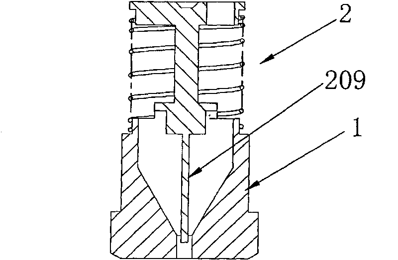
[0026] Such as image 3 , 4 shown.

[0027] A dual gas source gas nozzle, comprising an outer nozzle 1 and an inner nozzle 2, the nozzle body 101 of the outer nozzle 1 is provided with an air chamber 102 and a spray hole 103 communicating with the air chamber 102, the inner nozzle 2 It is composed of a valve rod 209, a connecting rod 203 and a return spring 204. One end of the valve rod 209 is connected to the connecting rod 203, and the other end of the valve rod 209 is movably inserted into the spray hole 104. The diameter of the spray hole 103 depends on the specific type of gas The diameter of the valve rod 209 depends on the flow requirements of a specific type of gas appliance for the high calorific value gas source. One end of the return spring 204 is in contact with the nozzle body 101, and the other end is in contact with the inlet on the connecting rod 203. Gas disc 205 offsets.

[0028] When the gas used was a high calorific value, the valve body in the inner noz...


PUM


Abstract

The invention discloses a gas nozzle with double gas source, comprising an outer nozzle (1) and an inner nozzle (2). The gas nozzle with double gas source is characterized in that an air chamber (102) and a nozzle (103) are arranged in the nozzle body (101) of the outer nozzle (1); the inner nozzle (2) is composed of an inner spray nozzle body (201), a seal ring (202), a connecting rod (203) and a return spring (204), wherein the inner spray nozzle body (201) is connected with one end of the connecting rod (203); the seal ring (202) is inserted on the inner spray nozzle body (201); one end of the return spring (204) is abutted with the nozzle body (101) of the outer nozzle (1); the other end of the return spring (204) us abutted with the bottom of an air inlet plate (205); an inner gas chamber (206) and an inner spray orifice (207) are arranged in the inner spray nozzle body (201); the inner spray orifice (207) is communicated with the inner gas chamber (206); the upper part of the inner spray nozzle body (201) is provide with an air inlet (208) communicated with the inner gas chamber (206). The invention has the advantages of small noise and convenient manufacture.

Description

technical field [0001] The invention relates to a gas appliance, in particular to a gas appliance that can use both high-calorific-value gas (such as liquefied petroleum gas) and low-calorific-value gas (such as natural gas and biogas, etc.), specifically a dual gas source gas nozzle. Background technique [0002] At present, with the continuous improvement of transportation technology and the increasing shortage of oil resources, natural gas, biogas and other low calorific value gases have gradually entered people's daily life, and the single energy source in cities is being gradually broken by the multi-energy supply system. At the same time, it has become possible to connect the gas supply pipelines of coal gas, natural gas, liquefied petroleum gas, biogas and other energy sources. People can choose the appropriate gas to use according to market price changes and gas supply conditions. Taking the gas heater as an example, in the past, it was a single structure dedicated t...

Claims


Application Information

Patent Timeline
Patent Type & Authority Applications(China)
IPC IPC(8): F23D14/48
Inventor 占义兵钱成明
Owner PROCOM ELECTRIC APPLIANCES SHANGHAI
Features
  • R&D
  • Intellectual Property
  • Life Sciences
  • Materials
  • Tech Scout
  • Unparalleled Data Quality
  • Higher Quality Content
  • 60% Fewer Hallucinations
Learn More