Exhaust method and device of thermal field of single crystal furnace

A technology of an exhaust device and an exhaust method, which is applied in the directions of single crystal growth, chemical instruments and methods, crystal growth, etc., can solve the problems of difficult cleaning of the pipe wall, increase the flow rate and flow rate of cooling water, and thermal field damage, etc. Solve the effect of heat loss, increase thermal insulation materials, and flexible disassembly

Inactive Publication Date: 2010-05-19
NAN AN SANJING SOLAR POWER
View PDF2 Cites 8 Cited by
  • Summary
  • Abstract
  • Description
  • Claims
  • Application Information

AI Technical Summary

Problems solved by technology

[0004] Disadvantages of the lower exhaust thermal field method in actual production: 1. Impurities produced by the reaction and volatilization of raw materials inside the crucible at high temperature are carried by the air flow, and the impurities and their volatiles are enriched on the heater when they pass through the heater , can easily lead to a short circuit or ignition of the heater, affecting production and even causing damage to the thermal field
At the same time, impurities will also be enriched on other parts of the thermal field, which will affect the service life of the parts; 2. A stable thermal field is required during the preparation of single crystal ingots. The air flow passes through the heater to take away the heat, and the temperature control loop system will pass through the PID The parameters automatically adjust the power and perform heat compensation, so it will cause temperature fluctuations in the crucible and affect crystal growth; 3. Because the air flow passes through the heater and the heat preservation cover, it takes away the heat of the heater and heat preservation cover, resulting in excessive loss of heat
[0005] In view of the above problems, the Chinese patent with the application number 01136561 titled "Airflow Control Method and Device for the Thermal Field of a Czochralski Silicon Single Crystal Furnace" proposed a solution, which is to set a guide between the heating element and the heat preservation cover. The trachea, the gas flow of argon gas containing silicon monoxide is discharged through the air guide tube of the sealed air guide device, and the impurities are no longer attached to the heating element, which can prolong the life of the heating element, but this method also has the following disadvantages: If the air duct is made of metal and other materials, since the air duct is located between the inner surface of the insulation cover and the heating element, the relatively low-temperature gas in the air duct will take away the heat from the heater and the insulation cover, which still cannot solve the problem of heat loss. The temperature fluctuation in the crucible affects the defect of crystal growth; if the air duct is made of some non-metallic insulation materials, it often needs to occupy a larger volume, which increases the volume of the entire insulation cover, and the corresponding required insulation materials also increase; In addition, impurities accumulate in the pipe body, the pipe is easily blocked, and the pipe wall is not easy to clean
However, in actual production, the exhaust method of directly evacuating from the upper part will cause the liquid surface to shake and the temperature of the liquid surface to be difficult to control
However, during the single crystal pulling process, the liquid surface shakes seriously, and the liquid surface temperature is slightly unstable, which will cause the single crystal to break (also known as the crystal line breaking, that is, the failure of pulling the crystal), or even fail to seed the crystal at all, or lead it out. polycrystalline
In addition, vacuuming directly against the liquid surface and pulling away the hot air will cause damage to the vacuum pipeline and vacuum pump. In order to avoid damage to the vacuum pipeline and vacuum pump, the flow and velocity of the cooling water must be increased, which will cause unnecessary work. loss

Method used


Image

  • Exhaust method and device of thermal field of single crystal furnace
  • Exhaust method and device of thermal field of single crystal furnace
  • Exhaust method and device of thermal field of single crystal furnace

Examples


Embodiment example 1

[0023] Before the exhaust port was changed, the 18-inch thermal field, the feeding amount was 65KG, the length of the six-inch single crystal growth was 1250mm, the production power was 70KW / hour, and the average use times of the graphite crucible was 18 furnaces. After using the design of the exhaust port, the feeding amount 76KG, can produce six-inch single crystal length 1550mm, production power 58 to 62KW / hour, the average number of times of use of graphite crucible with the same mechanism size increased to 35 furnaces.

Embodiment example 2

[0025] Before the exhaust port was changed, the thermal field was 20 inches, the feeding amount was 80KG, the length of the six-inch single crystal was 1650mm, the production power was 75KW / hour, and the graphite crucible was used for an average of 20 furnaces. After using this design of the exhaust port, the feeding amount 100KG, can produce six-inch single crystal length 2100mm, production power 62 to 66KW / hour, the average use times of graphite crucible with the same mechanism size increased to 40 furnaces.


PUM


Abstract

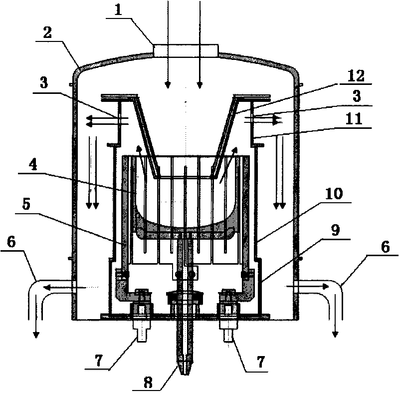
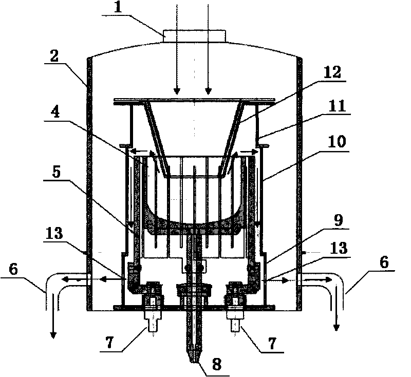
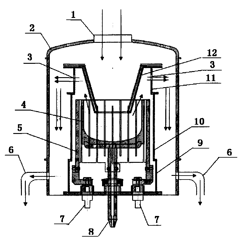
The invention relates to an exhaust method and a device of a thermal field of a single crystal furnace, and an upper exhaust port is formed on an upper thermal insulation cover of the thermal field of the single crystal furnace for leading air flow to flow out from the upper exhaust port, enter into an air extraction pipeline through a gap between the thermal insulation cover and a furnace wall and be pumped by a vacuum pump. The device comprises the furnace wall, a graphite crucible, a quartz crucible, a heater, the thermal insulation cover and a flow guide cylinder and is characterized in that the thermal insulation cover comprises an upper thermal insulation cover, a main thermal insulation cover and a lower thermal insulation cover, the upper exhaust port is formed on the upper thermal insulation cover, and the gap is maintained between the furnace wall and the thermal insulation cover. Due to that an exhaust air flow channel in the thermal field does not pass through the heater at the bottom, the device can not cause the meaningless heat loss, be more energy-saving in comparison with the original lower exhaust thermal field and simultaneously improve the production efficiency.

Description

technical field [0001] The invention relates to a method and a device for exhausting a heat field of a single crystal furnace, in particular to a method and a device for exhausting a heat field in a Czochralski method (Czochralski method) for growing a single crystal silicon. Background technique [0002] The basic principle of Czochralski single crystal is that the high-purity silicon material is heated and melted, and when the temperature is suitable, the steps of immersing the seed crystal, welding, seeding, shouldering, turning the shoulder, equal diameter, and finishing are completed to complete the pulling of a single crystal rod. system. [0003] In the prior art, high-purity argon gas is injected from the top of the single crystal furnace, and the gas is drawn out by a vacuum pump at the bottom, and the vacuum value in the furnace maintains a dynamic balance (generally around 10-15mbar). For the exhaust process of this process, see figure 2 As shown by the arrow, a...

Claims


Application Information

Patent Timeline
Patent Type & Authority Applications(China)
IPC IPC(8): C30B15/20
Inventor 南毅张伟娜郑智雄林霞胡满根
Owner NAN AN SANJING SOLAR POWER
Why Eureka
Try Eureka