Eureka AIR delivers breakthrough ideas for toughest innovation challenges, trusted by R&D personnel around the world.

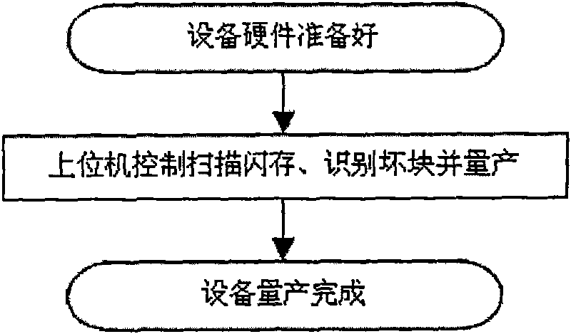
Equipment production flow using flash memory as storage medium

A storage medium and production process technology, applied in static memory, electrical program control, comprehensive factory control, etc., can solve the problems of increased read and write workload, long time spent, increased time cost, etc., and achieve large-scale batch production The effect of production, improving production efficiency, and increasing production quantity

Active Publication Date: 2010-05-19
SHENZHEN NETCOM ELECTRONICS CO LTD
View PDF0 Cites 7 Cited by
  • Summary
  • Abstract
  • Description
  • Claims
  • Application Information

AI Technical Summary

Problems solved by technology

With the development and progress of semiconductor technology, the single-chip capacity of flash memory has increased rapidly, which greatly increases the workload of reading and writing in the scanning process; and the wide adoption of MLC (Multi-Level Cell multi-layer cell structure) Due to the storage density of flash memory, it takes longer and longer to completely scan a piece of flash memory, resulting in lower and lower output (production efficiency) of the lower computer per unit time; production costs, especially time costs, have increased significantly

Method used


Image

  • Equipment production flow using flash memory as storage medium
  • Equipment production flow using flash memory as storage medium
  • Equipment production flow using flash memory as storage medium

Examples


Embodiment Construction

[0015] The specific method of the present invention will be described in detail below in conjunction with the accompanying drawings.

[0016] The lower computer production (i.e. production method) of the present invention only refers to scanning the flash memory in the lower computer and solidifying the firmware program, and does not include physical assembly.

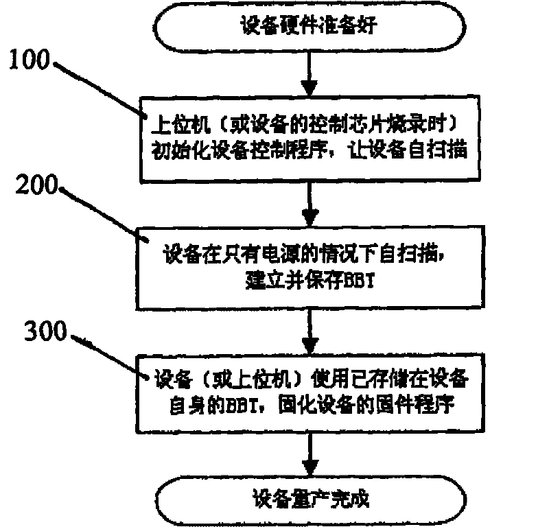
[0017] The focus of the present invention is to improve the production mode under the traditional technology, and change the traditional mode of scanning the flash memory of the lower computer from the empty machine of the upper computer to the self-scanning method of the lower computer. That is to say, after the lower computer is separated from the upper computer, it can scan by its own control chip under the condition of only power supply.

[0018] In the present invention, the concept of bad block table BBT is introduced, which refers to the collection of records of good and bad conditions of each "block" in the fla...


PUM


Abstract

The invention relates to an equipment production flow using a flash memory as a storage medium. The production flow comprises the following steps that: A, the equipment using the flash memory as the storage medium is used as a lower computer to be connected to a special production machine used as an upper computer, and the upper computer writes a control program in the lower machine; B, under a condition of being disconnected from the upper computer, the lower computer automatically scans and establishes and stores a bad block table BBT; and C, according to the BBT stored in the lower computer, the upper computer solidifies the proper firmware program to the lower computer. In the production flow, the bad blocks in the lower computer are scanned by the lower computer and the resources of the lower computer are not occupied, so that the condition that the upper computer is idled to wait is hardly happened. Just by being connected with a power supply, the lower computer can complete the scanning process; and if the productivity needs to be increased, the productivity increase can be achieved just by adding proper number of power supplies, so that the units of product of the lower computer in unit time are greatly increased, the production efficiency is greatly improved, and the time cost and the labor cost are lowered.

Description

technical field [0001] The invention relates to a production flow of equipment using flash memory as a storage medium. Background technique [0002] Flash memory (Flash), also known as flash memory, is a non-volatile memory. In the case of power failure, the information of its internal unit can still be saved. And because it has the advantages of high storage density, low price, and fast unit reading speed, it is widely used in electronic products as a memory to store system programs and data information. These electronic products or devices include, but are not limited to, USB (Universal Serial Bus) Disk, MP3, MMC (Multi Media Card), SD (Security Card), CF ( Compact Flash) card, MS (Memory Stick), PMP (Portable Music Player), SSD (Solid State Disk). figure 1 is the functional block diagram of these electronic products or devices. [0003] A flash memory usually contains several "blocks" (Block). Restricted by factors such as technology and process, some "blocks" of the...

Claims


Application Information

Patent Timeline
Patent Type & Authority Applications(China)
IPC IPC(8): G05B19/418G11C29/00
CPCY02P90/02
Inventor 李中政李志雄
Owner SHENZHEN NETCOM ELECTRONICS CO LTD
Why Eureka
Eureka Blog
Learn More