Double-wing type combined trajectory energy dissipation structure

An energy dissipator and double-fin technology, which is applied in the field of flood discharge and energy dissipation facilities, can solve the problems of increasing project investment and construction period, increasing the amount of protection works, and difficulty in returning water to the trough, so as to save project investment and construction period, and reduce construction difficulty. The effect of small, excavation reduction

Inactive Publication Date: 2010-05-26
SICHUAN UNIV
View PDF0 Cites 11 Cited by
  • Summary
  • Abstract
  • Description
  • Claims
  • Application Information

AI Technical Summary

Problems solved by technology

When building a water cushion pond, it is necessary to excavate the downstream bank slope. Due to the steep slopes on both sides, the construction of the water cushion pond is not only difficult to construct, but also has a considerable amount of excavation, which incre...

Method used


Image

  • Double-wing type combined trajectory energy dissipation structure
  • Double-wing type combined trajectory energy dissipation structure
  • Double-wing type combined trajectory energy dissipation structure

Examples


Embodiment Construction

[0021] The structure of the double-fin combined jet energy dissipater of the present invention will be further described below in conjunction with the accompanying drawings.

[0022] The double-wing type combined jet energy dissipater in this embodiment is based on the design of a hydropower station's pivotal project. The power station is located in a narrow river valley section with steep slopes on both banks. The downstream of the hydropower station is connected to a cushion pond. 23 degree corner.

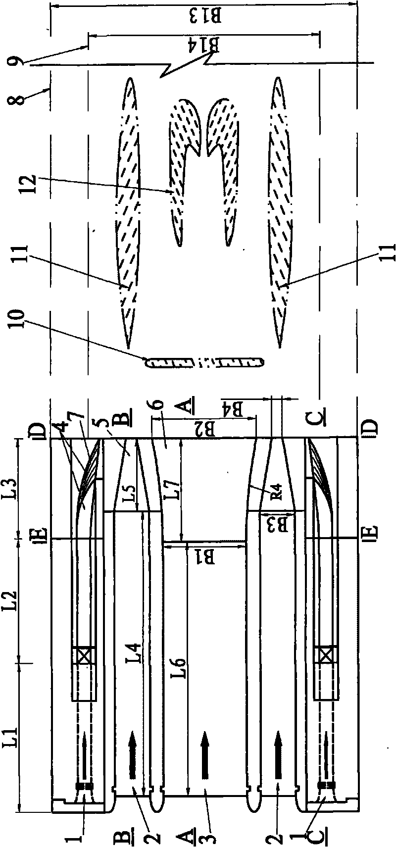
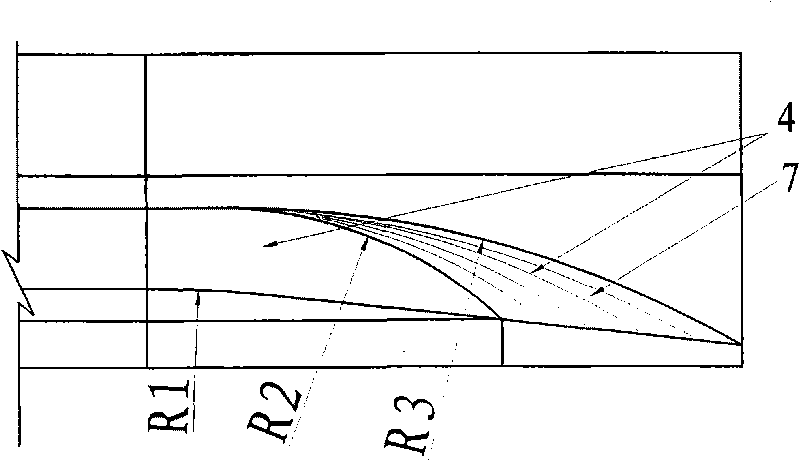
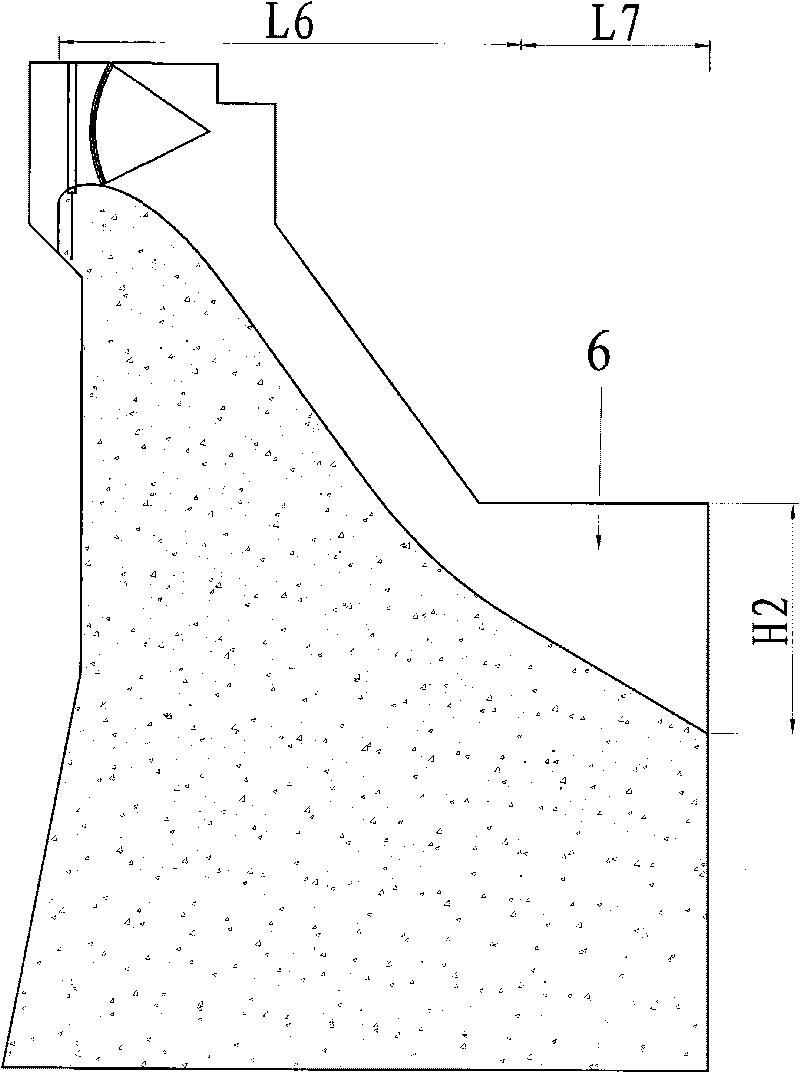
[0023] The structure of the double-fin combined jet energy dissipater in this embodiment is as follows figure 1 , figure 2 , image 3 , Figure 4 , Figure 5 , Image 6 , Figure 7 As shown, it includes a central overflow groove 3, a structure located on both sides of the central overflow groove, two overflow side grooves of the same size 2, a structure respectively located outside the two overflow side grooves, and two discharge bottom holes 1 of the same size. . The outlet of the...


PUM


Abstract

The invention discloses a double-wing type combined trajectory energy dissipation structure, which comprises a central overflow groove, and an overflow side groove and a water discharging bottom hole which are orderly positioned on two sides of the central overflow groove; an outlet of the central overflow groove is provided with a planar diffusion continuous step-down; an outlet of the overflow side groove is provided with a shrinkage slotted flip bucket; and an outlet of the water discharging bottom hole is provided with a warped deflecting bucket. The energy dissipation structure can reduce the width of a downstream plunge pool, improve the state of flow of the plunge pool, and save construction cost and period.

Description

Technical field [0001] The invention belongs to a flood discharge and energy dissipation facility, and particularly relates to an energy dissipation device used for narrow river valley terrain and matched with water cushion ponds. Background technique [0002] To build a hydropower station in a narrow river valley, the energy dissipaters supporting the water cushion pond usually include a central overflow trough, overflow side troughs and bottom discharge holes located on both sides of the central overflow trough. The outlet of the central overflow trough is provided with a symmetrical diffusion sill, or only a narrow slit sill is provided at the exit of the overflow side trough, so the width of the downstream water cushion pool is relatively large. When constructing the plunge pool, excavation should be carried out on the downstream bank slope. Due to the steep slopes on both sides, the construction of the plunge pool is not only difficult to construct, but also requires a consi...

Claims


Application Information

Patent Timeline
IPC IPC(8): E02B8/06
Inventor 张建民刘善均张宗亮李云杨宜文许唯临王韦戈莉琼曲景学邓军田忠李忠任成瑶陈剑刚李进牛志攀雷刚
Owner SICHUAN UNIV
Why Eureka
Try Eureka