Multitube pulse detonation combustion chamber communicated with jet deflector
A technology of pulse detonation and detonation combustion, which is applied to machines/engines, jet propulsion devices, rocket engine devices, etc., can solve the problems of hindering detonation frequency, unstable performance, and high-power ignition and detonation devices, etc. Avoid premature ignition and continuous combustion, improve cycle efficiency, and increase the effect of operating frequency
- Summary
- Abstract
- Description
- Claims
- Application Information
AI Technical Summary
Problems solved by technology
Method used
Image
Examples
Embodiment 1
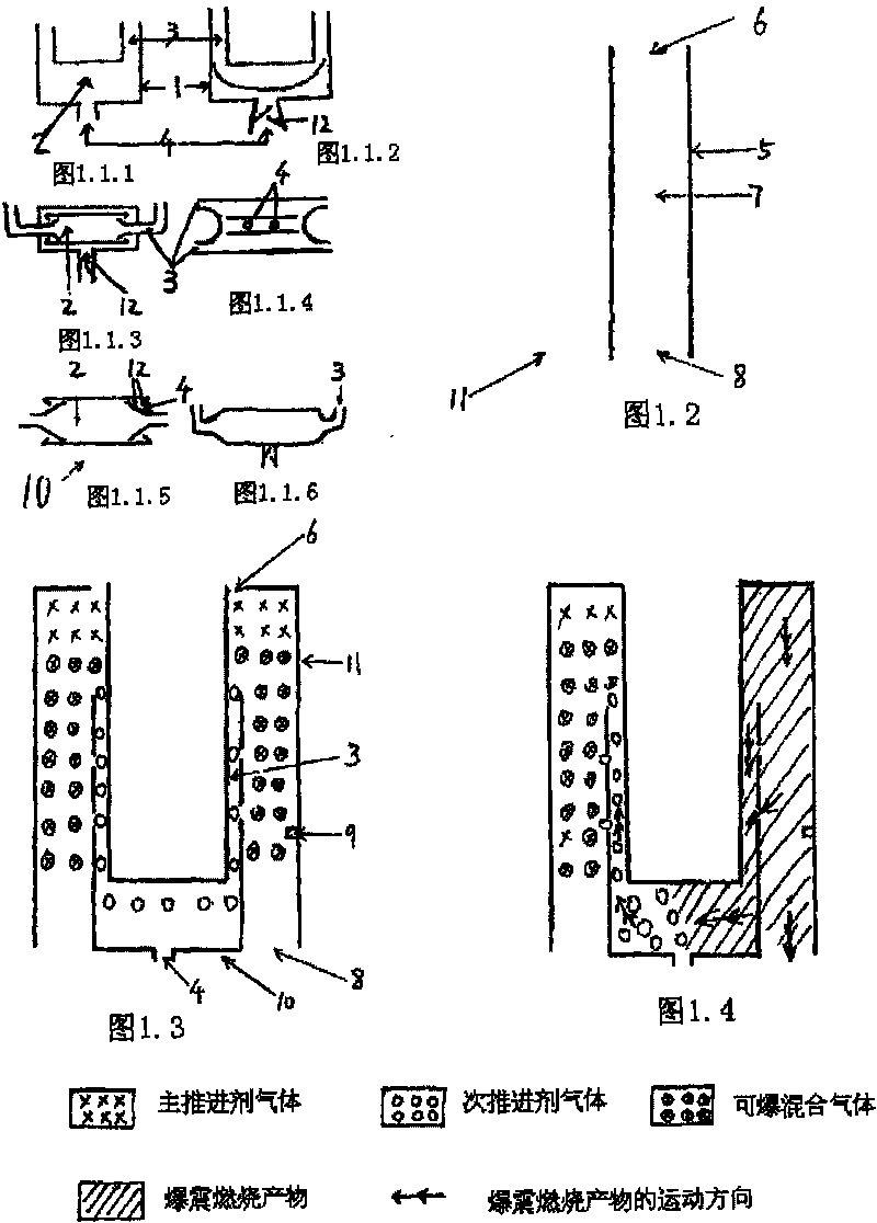
[0046] Embodiment 1: (see attached Figure 1.3 ) A detonation transponder 10 connects two sets of detonation units 11 side by side through its two connecting pipes 3 to form a group, and a detonation transponder 10 is located in the detonation chamber of the two parallel detonation units 11 Near the outlet 8, each connecting pipe 3 enters the inner chamber of each set of detonation units 11 from the vicinity of the outlet 8 of the downstream detonation chamber of the two sets of detonation units 11, and an ignition and detonation device 9 is installed on the right side of the set of detonation units. In the detonation chamber 7 of the shock unit 11, the detonation chamber outlet 8 of every set of detonation units 11 is all communicated with the outside world, and the cross-sectional area of the connecting pipe 3 in the same cross section is 20% of the detonation unit 11 cross-sectional area.
[0047] Before starting the detonation, the main propellant air enters the detonati...
Embodiment 2
[0049] Embodiment 2: (see attached Figure 2.1 ) Two sets of detonation units 11 are connected side by side to form a group by two detonation transponders 10 through their connecting pipes 3, and an ignition detonation device 9 is installed in the detonation chamber 7 of one set of detonation units 11, wherein A detonation transfer injector 10 is used for injecting the JP10 fuel of sub-propellant ethylene and atomization, and it is located near the detonation chamber outlet 8 of two sets of detonation units 11 side by side. The two detonation transfer injectors 10 Two connecting pipes 3 enter the inner cavity of each set of detonation units 11 from the vicinity of the detonation chamber outlet 8 located downstream of the two sets of detonation units 11, and the other detonation transfer injector 10 is used for injecting and filling the main propellant air, Near the entrance 6 of the detonation chamber of two sets of detonation units 11 juxtaposed, its propellant inlet 4 commun...
Embodiment 3:( pic 3)810311 1 , 1 1179,118 and 。 1 10, 1 10,10311811,116,“6”103。 and Embodiment 2, 1 11,,,10, and 2 1 117,、。 1 1 。 Embodiment 4
[0050] Embodiment 3: (see attached image 3 ) Two sets of detonation units 11 are connected side by side to form a group by two detonation transponders 10 that are all located near the detonation chamber outlet 8 through their connecting pipes 3, and the detonation chamber 7 of one set of detonation units 11 is An ignition and detonation device 9 is installed inside, and the detonation chamber outlet 8 of each set of detonation unit 11 is all communicated with the outside world. One of the detonation injectors 10 is used to inject secondary propellant, and the other detonation injector 10 is used to inject and inject main propellant. The set of detonation units 11 near the outlet 8 of the downstream detonation chamber enters the inner cavity of each set of detonation units 11, and the original detonation chamber entrance 6 upstream of the inner cavities of the two sets of detonation units 11 is closed, and the "new detonation chamber The inlet 6" is equivalent to the two conn...
PUM
 Abstract
Description
Claims
Application Information
 - R&D
- Intellectual Property
- Life Sciences
- Materials
- Tech Scout
- Unparalleled Data Quality
- Higher Quality Content
- 60% Fewer Hallucinations
Browse by: Latest US Patents, China's latest patents, Technical Efficacy Thesaurus, Application Domain, Technology Topic, Popular Technical Reports.
© 2025 PatSnap. All rights reserved.Legal|Privacy policy|Modern Slavery Act Transparency Statement|Sitemap|About US| Contact US: help@patsnap.com


