
Combined testing device and testing method of laser damage thresholds of film and optical element

A technology of laser damage threshold and optical components, which is applied in the direction of optical testing of flaws/defects, testing of optical properties, measurement of scattering characteristics, etc. It can solve problems such as large errors in test results, poor practicability, and misjudgment of the adaptability of various thin film materials. , to achieve the effect of extreme error and strong adaptability

Active Publication Date: 2010-06-02
XIAN TECHNOLOGICAL UNIV
View PDF0 Cites 54 Cited by
  • Summary
  • Abstract
  • Description
  • Claims
  • Application Information

AI Technical Summary

Problems solved by technology

[0006] The object of the present invention is to provide a combination test device and test method for laser damage threshold of thin film and optical elements, to overcome the large error in the test results in the prior art, the possibility of misjudgment and poor adaptability to various thin film materials, Therefore, the problem of poor practicality

Method used


Image

  • Combined testing device and testing method of laser damage thresholds of film and optical element
  • Combined testing device and testing method of laser damage thresholds of film and optical element

Examples


Embodiment Construction

[0018] Below in conjunction with accompanying drawing, the present invention will be further described.

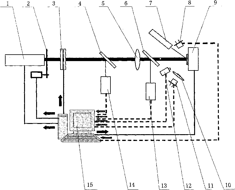
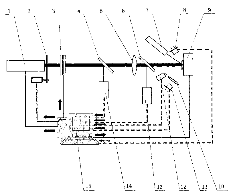
[0019] see figure 1 , a thin film and optical element laser damage threshold combined testing device, including a testing component and a processing component. The test components include a Nd:YAG laser 1 arranged on a main optical axis, a switch baffle 2, an attenuator 3, a first beam splitter 4, a focusing lens 5, a second beam splitter 6, an auxiliary laser 7, a photoelectric Diode array 8 , sample stage 9 , converging lens 10 , photodetection device 11 , CCD camera 12 , beam profiler 13 and energy meter 14 . Wherein the auxiliary laser 7 is set at 45 degrees away from the main optical axis, and its emission beam is towards the sample stage 9, and the said CCD camera 12 is arranged in the area between the auxiliary laser 7 reflected light beam and the main optical axis; the said photodiode array 8 is located at In the cone angle of 60 degrees of the sample surface nor...


PUM


Abstract

The invention relates to a combined testing device of the laser damage thresholds of a film and an optical element and a testing method utilizing the device. The traditional testing device and testing method have greater error and poor suitability for various film materials. The combined testing device of the laser damage thresholds of a film and an optical element comprises a testing assembly and a processing assembly, wherein the testing assembly comprises a Nd:YAG laser, a switch baffle, a first beam splitter, a focusing lens, a second beam splitter, a sample platform, a photodiode array, a convergent lens, an optoelectronic detector, a CCD camera, and the like; and the processing assembly comprises a computer. The testing method comprises the step of: conveying a testing result to judge whether various types of film samples are damaged or not by a CCD video microscopy judging method and a plasma flashing method according to a judgment criterion that one displayed damage is conformed The structure and the testing method of the invention has minimum testing error without error judgments and strong suitability and practicability.

Description

Technical field: [0001] The invention relates to the technical field of a laser damage threshold testing device for the surface of a thin film or an optical element, in particular to a combination testing device and a testing method for a laser damage threshold of a thin film and an optical element. technical background: [0002] In high-power and high-energy laser systems, there are a large number of thin-film components, and the ability of these components to resist laser damage is closely related to the normal and effective operation of the system. Previous studies have shown that the damage of thin film components under strong laser is completely determined by the anti-laser ability of the thin film on the surface of the component. Therefore, with the continuous expansion of the application range of high-power lasers, the importance of thin film anti-laser damage performance has become increasingly prominent, so that the laser damage threshold has become an indispensable...

Claims


Application Information

Patent Timeline
IPC IPC(8): G01N21/88G01N21/49G01M11/02
Inventor 苏俊宏徐均琪梁海锋杨利红惠迎雪杭凌侠朱昌
Owner XIAN TECHNOLOGICAL UNIV
Learn More