Method and device for detecting position of rotor of brushless motor

A rotor position, brushless motor technology, applied in the direction of electronic commutator, etc., can solve the problems of no fault tolerance function, brushless motor rotor position detection method is difficult to meet, reliability is difficult to guarantee, etc.

Inactive Publication Date: 2010-06-02
NANTONG WANBAO IND +1
View PDF0 Cites 38 Cited by
  • Summary
  • Abstract
  • Description
  • Claims
  • Application Information

AI Technical Summary

Problems solved by technology

The absolute grating encoder directly converts the angle of the rotating shaft into a digital signal, which is simple and convenient to use, but it is difficult to be widely used due to factors such as environmental adaptability and price; the Hall sensor has a simple structure, but it is difficult to meet the requirements of high-precision angle measurement and is limited. Resolvers are widely used in high-precision servo systems due to their reliable structure, good real-time performance, and strong environmental adaptability.
[0004] At present, in a large number of documents and patents at home and abroad, the research on the rotor position detection of brushless motors is limited to the conditioning method of the position signal, and the research on the reliability of the rotor position detection of brushless motors is limited to the Hall position sensor. The rotor position detection method of the brushless motor of the transformer is difficult to meet the high reliability requirements of national defense and aerospace.
[0005] When a resolver is used as the rotor position detection device of a brushless motor, the resolver outputs two high-frequency sinusoidal signals that contain rotor position information and are orthogonal to each other. The rotor position information must be obtained through signal conditioning or calculation methods, which is currently the most widely used. It is widely used integrated chips such as dedicated Resolver-to-Digital Converter (RDC) plus peripheral configuration circuits for solving. Such special solving chips are sensitive to signals and have no fault tolerance function, so the reliability Difficult to guarantee

Method used


Image

  • Method and device for detecting position of rotor of brushless motor
  • Method and device for detecting position of rotor of brushless motor
  • Method and device for detecting position of rotor of brushless motor

Examples


Embodiment Construction

[0044] Now in conjunction with embodiment, accompanying drawing, the present invention will be further described:

[0045] Implementation example of the device of the present invention:

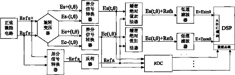
[0046] The detection device is divided into two parts: a resolver installed coaxially with the rotor of the brushless motor under test and a resolver signal conditioning circuit. The resolver signal conditioning circuit includes a sinusoidal excitation circuit as a resolver signal source and self-monitoring and fault-tolerant algorithm signal conditioning. circuit (contains differential signal converter, precision absolute value adder, inverter, and low-pass filter).

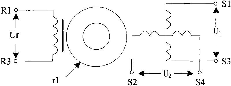
[0047] Schematic diagram of the rotary transformer figure 2 As shown, the resolver rotor r1 is installed coaxially with the motor rotor, Ur is the input end of the excitation signal, U1 and U2 are the output ends of the sine signal and cosine signal respectively.

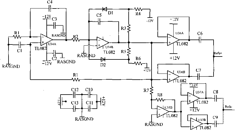
[0048] The sinusoidal excitation circuit uses a modified Wie...


PUM


Abstract

The invention relates to a method and a device for detecting the position of a rotor of a brushless motor, which are characterized in that a rotary transformer and the rotor of a tested brushless motor are arranged coaxially, the rotary transformer outputs two paths of orthogonal high-frequency sine-cosine signals containing information about the position of the rotor, and the information about the position of the rotor is obtained by the methods such as signal conditioning or resolving and the like. The most widely applied integrated chip at present adopting a special Resolver-to-Digital converter (RDC for short) and the like and a peripheral configuration circuit are used for performing resolving, and a special resolving chip of the type is sensitive to signals and has no fault-tolerant function, so the reliability is difficult to guarantee. The device of the invention is provided with a simple signal conditioning circuit on the basis of an RDC functional circuit to realize the detection of the position of the rotor of the brushless motor with self-monitoring and fault tolerance functions.

Description

technical field [0001] The invention relates to a method and a device for detecting the rotor position of a brushless motor, belonging to a method and a device for detecting the rotor position of a brushless motor control system. Background technique [0002] One of the key technologies of the brushless motor control system is the detection of the rotor position. Only after the actual spatial position (absolute position) of the rotor is detected, the control system can determine the power-on mode, control mode, and frequency and phase of the output current of the inverter. To ensure the normal operation of the brushless motor. Therefore, an accurate rotor position detection device is very important. Once the position detection device fails, the commutation logic of the motor will be confused, the output torque will decrease, the speed will decrease until it stops. In some occasions with high reliability requirements or certain specific occasions, such as: national defense,...

Claims


Application Information

Patent Timeline
Patent Type & Authority Applications(China)
IPC IPC(8): H02P6/16
Inventor 周奇勋李声晋卢刚刘鹏周勇季新杰张举中赵凯张玉峰
Owner NANTONG WANBAO IND
Why Eureka
Try Eureka